Festo DGSL-10-50-Y3A Käyttöohje

Festo Ei luokiteltu DGSL-10-50-Y3A

Lue alta 📖 käyttöohje suomeksi merkille Festo DGSL-10-50-Y3A (4 sivua) kategoriassa Ei luokiteltu. Tämä opas oli hyödyllinen 2 henkilölle ja sai 4.5 tähden keskimäärin 2 käyttäjältä

Sivu 1/4
DGSL
Mini slide
Festo SE & Co. KG
Ruiter Straße 82
73734 Esslingen
Deutschland
+49 711 347-0
www.festo.com
Operating instructions
8166553
2021-11i
[8166555]
Translation of the original instructions
© 2021 all rights reserved to Festo SE & Co. KG
1 Applicable Documents
All available documents for the product
è www.festo.com/sp.
2 Safety
2.1 Safety instructions
Take into account the ambient conditions at the location of use.
Only use the product in its original condition without unauthorised modifica-
tions.
Observe the identifications on the product.
Store the product in a cool, dry environment protected from UV and corrosion.
Keep storage times short.
Before working on the product, switch off the compressed air supply and lock it
to prevent it from being switched on again.
Have the product repaired by the Festo repair service only.
Observe the tightening torques. Unless otherwise specified, the tolerance is
± 20%.
2.2 Intended use
The product is intended for the space-saving transport of masses. The product is
approved for slide operating mode.
Fig.1
2.3 Foreseeable misuse
Operating the product without cushioning components will result in damage.
The product may be destroyed if the slide is moved without a (fixed) stop.
Use suitable cushioning components
è www.festo.com/catalogue.
2.4 Training of qualified personnel
Work on the product may only be carried out by qualified personnel who can
evaluate the work and detect dangers. The qualified personnel have skills and
experience in dealing with pneumatic (open-loop) control technology.
3 Additional information
Contact the regional Festo contact if you have technical problems
è www.festo.com.
Accessories and spare parts è www.festo.com/catalogue.
4 Function
The product is a non-rotating single-piston drive with bearing guide.
The slide is moved back and forth by alternate pressurisation of the supply ports.
The slide is braked at the end position by shock absorbers.
For DGSL-...-E/-P/-P1: by external elastic shock absorbers.
For DGSL-...-Y3/-Y11: with external hydraulic shock absorbers.
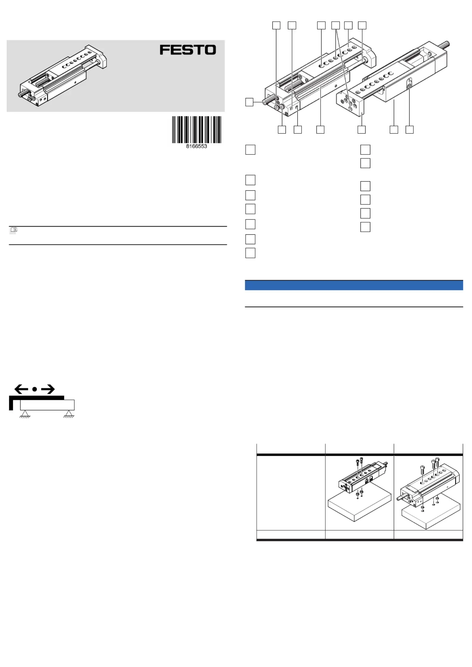
5 Product design
1
4 5 6 7
8910111213
2 3
Fig. 2: Product design
1
Cushioning component:
- DGSL-...-E/-P/-P1: elastic
- DGSL-...-Y3/-Y11: hydraulic
- DGSL-...-N: without
2
Supply port: retract, with plug
screw
3
Supply port: advance
4
Drilled hole for mounting the
mini slide, concealed
5
Thread with centring recess for
mounting the payload
6
Slide with bearing guide
7
Piston rod
8
(Fixed) stop
9
Thread with centring recess for
mounting the mini slide, con-
cealed
10
Yoke plate
11
Slots for proximity switches
12
Supply port: retract
13
Supply port: advance, with plug
screw
6 Transport and storage
NOTICE
Unexpected and unbraked movement of components
Secure moving components for transport.
Do not store near magnets.
7 Assembly
7.1 Preparation
Position the product to ensure that the operating elements are accessible,
e.g. the clamping components for the shock absorbers.
Mount the product without torsional stresses.
If necessary: select the mounting components or the accessories.
To prevent collisions: mount the mounting components outside the positioning
range.
7.2 Mounting
1. Select a suitable adapter plate.
2. To make the through-holes accessible, move the slide to the retracted end
position.
3. Use the included centring sleeves.
4. Mount the product according to the type of mounting according to stroke.
DGSL-... -10 … -40 -50 … -200
Base-surface mounting with
Through-holes
Centring recess and cen-
tring sleeves
Required retaining screws 2 3
7.3 Attachment
7.3.1 Attachment of yoke plate
2
34
1
Fig. 3: Securing yoke plate
1
Housing
2
Yoke plate
3
Metal plate
4
Centring pins
1. Push a metal plate [3] between the yoke plate [2] and the housing [1] as a
counter holder.
2. Press the centring pins [4] manually into the yoke plate.
Do not hammer in the centring pins.
7.3.2 Attaching the payload
1
2
3
Fig. 4: Attachment of the payload
1
Yoke plate
2
Centring pins
3
Retaining screws
1. Position the payload on the yoke plate [1] .
2. Fasten the payload with the retaining screws [3].
8 Installation
8.1 Installation of proximity switches
To avoid faulty switching and external influences, observe the minimum distances
L1 and L2 between the static and moving ferritic masses and proximity switches.
Fig. 5: Minimum distances
DGSL-... -4 -6 -8 -10 -12 -16 -20 -25
L1
to ferritic materials [mm] 5 5 0
L2
to ferritic materials [mm] 15 0
Tab. 1: Minimum distances
1
Fig. 6: Position detection with proximity switch
1
Slots for proximity switches
1. Position the proximity switches in the slots [1].
Use the lower slot for the DGSL-...-4 and DGSL-...-8 products.
2. Temporarily lock the proximity switch.
3. After the test run, mount the proximity switch in the suitable position.
8.2 Rough setting of end positions
1. Position the slide at the desired end position by hand. Leave the slide in the
retracted end position during the setting procedure.
2. Unscrew the retaining screws of the (fixed) stop and the orifice .1 2
Certain product variants allow coarse adjustment of the front-end position
è www.festo.com/catalogue.
A stroke reduction of max. 2 standard strokes is possible in combination
with the precision adjustment.
3. Replace the (fixed) stop with the orifice .1 2
1
2
4. Screw in the retaining screws. Observe the tightening torque.
DGSL-... -4 -6 -8 -10 -12 -16 -20 -25
Tightening torque [Nm] 0.76 1.3 1.3 2.9 2.9 6 9 9
5. Carry out the precision adjustment of the end positions on the cushioning
components.
8.3 Installation of cushioning components
Cushioning components for the DGSL-…-N product must be attached at both end
positions.
Fig. 7: Minimum distance L of the cushioning components
DGSL-... -4 -6 -8 -10 -12 -16 -20 -25
Distance L with
DGSL-...-E/-P/-P1
[mm] 1 1.5
Distance L with
DGSL-...-Y3/-Y11
[mm] – – 1.5
Tab. 2: Minimum distances
6.
DGSL-...-E/-P DGSL-...-P1 DGSL-...-Y3/-Y11
no metallic stop metallic stop
The rubber buffer touches the
slide.
The stop sleeve touches the
slide against the force of the
cushioning.
The shock absorber housing/
reducing sleeve (with DGSL-...-
Y11) touches the slide against
the force of the shock absorber.
Tab. 3: End position cushioning components
DGSL-... -4 -6 -8 -10
Only for DGSL-...-Y3
Max. torque, cushioning com-
ponent
[Nm] – 0.5 0.8
Shock absorber DYSW-...-Y1F [Nm] 4 … 6 5 … 8
Only for DGSL-...-Y11
Max. torque reducing sleeve [Nm] 0.8
Max. torque cushioning com-
ponent
[Nm] – – – 0.5
Shock absorber DYSW-...-Y1F [Nm] 4 … 6
Tab. 4: Tightening torque
DGSL-... -12 -16 -20 -25
Only for DGSL-...-Y3
Max. torque, cushioning com-
ponent
[Nm] 2.2 5 8 13
Shock absorber DYSW-...-Y1F [Nm] 7 … 10 8 … 14 10 … 17 12 … 20
Only for DGSL-...-Y11
Max. torque reducing sleeve [Nm] 2.2 5 8 13
Max. torque cushioning com-
ponent
[Nm] 0.8 2.2 5 8
Shock absorber DYSW-...-Y1F [Nm] 5 … 8 7 … 10 8 … 14 10 … 17
Tab. 5: Tightening torque
9 Commissioning
9.1 Precision adjustment of the end positions
Note
Check the correct positioning of the slide under compressed air. Correct the
positioning.
1
Fig. 8: Position of the clamping
components
1
Clamping components
1. Loosen the clamping components [1].
2. Position the slide at the desired end position by hand.
3. Turn the cushioning component with a hex wrench until the end position is
reached.
4. Tighten the clamping component.
DGSL-... -4 -6 -8 -10 -12 -16 -20 -25
Tightening torque of
clamping component
[Nm] 0.15 0.2 0.3 0.8 1.2 2.5 2.5 3.5
9.2 Test run
Fig. 9: Positioning payload
1. Position the payload on the slide. Position the centre of gravity of the payload
as low as possible.
2. Close the one-way flow control valves.
3. Open the one-way flow control valves by one revolution.
4. Pressurise the drive. Slowly pressurise with an on-off valve.
ÄThe slide moves to an end position.
5. Start a test run with a moveable mass.
Take the following into account in the test run:
The speed and the acceleration of the moveable mass
The end position
The mass of the payload
The position of the proximity switches
7. Only make changes when the slide is stationary.
8. Unscrew the one-way flow control valves until the required speed of the slide
is reached.
An increased speed when approaching the end position can result in the slide
rebounding from the end position.
9. Fix the proximity switches in the final positioning position.
10 Maintenance
10.1 Replacement of cushioning components
Fig. 10: Cushioning distance s
1. Check the cushioning elements every 2 million cycles.
2. Check the cushioning length s
è 12 Technical data
3. Replace the cushioning components if there are signs of wear.
4. Replace the cushioning components after max. 5 million cycles.
10.2 Cleaning
Clean the product with a clean, soft cloth and non-abrasive cleaning agents.
For use with reduced particle emission:
Remove abraded particles and soil from the product:
Prior to initial commissioning
Regularly during operation
10.3 Lubrication
Note
Check the need for shorter lubrication intervals:
At high temperatures.
With excessive dirt accumulation.
In the vicinity of grease-dissolving liquids or grease-dissolving vapours.
1. Lubricate the product as required.
2. Lubricate the piston rod and the guide rail.
Use the following lubricant:
Festo LUB-KC1
3. Move the slide by hand for even lubrication.

Tuotetiedot

Merkki: Festo
Kategoria: Ei luokiteltu
Malli: DGSL-10-50-Y3A

Tarvitsetko apua?

Jos tarvitset apua merkille Festo DGSL-10-50-Y3A esitä kysymys alla ja muut käyttäjät vastaavat sinulle


Ei luokiteltu Festo Käyttöohjeet

Ei luokiteltu Käyttöohjeet

Viimeisimmät Ei luokiteltu Käyttöohjeet