Festo EPCC-BS-60-400-5P-A Käyttöohje

Festo Ei luokiteltu EPCC-BS-60-400-5P-A

Lue alta 📖 käyttöohje suomeksi merkille Festo EPCC-BS-60-400-5P-A (6 sivua) kategoriassa Ei luokiteltu. Tämä opas oli hyödyllinen 2 henkilölle ja sai 4.5 tähden keskimäärin 2 käyttäjältä

Sivu 1/6
EPCC-BS
Electric cylinder
Festo SE & Co. KG
Ruiter Straße 82
73734 Esslingen
Deutschland
+49 711 347-0
www.festo.com
Operating instructions
8172502
2022-03c
[8172504]
Translation of the original instructions
© 2022 all rights reserved to Festo SE & Co. KG
1 Applicable Documents
All available documents for the product
è www.festo.com/sp.
2 Safety
2.1 Safety instructions
Observe labelling on the product.
Before working on the product, switch off the power supply and secure it
against being switched on again.
Store the product in a cool, dry environment protected from UV and corrosion.
Keep storage times short.
Store the product in ambient conditions without oils, greases and grease-dis-
solving vapours.
2.2 Intended Use
The electric cylinder is intended to be used for positioning payloads in combina-
tion with tools or as a drive when external guides are used.
2.3 Training of qualified personnel
Work on the product may only be carried out by qualified personnel who can
evaluate the work and detect dangers. The qualified personnel have knowledge
and experience in dealing with electric drive systems.
3 Additional information
Contact the regional Festo contact if you have technical problems
è www.festo.com.
Accessories and spare parts è www.festo.com/catalogue.
4 Product overview
4.1 Function
The electric cylinder converts the rotary motion of the mounted motor into a linear
motion of the non-rotating piston rod. The lead screw converts the torque of the
motor into a feed force. The linear movement of the piston rod is guided by the
guide in the guide ring. Sensors enable the monitoring of end positions, reference
position and intermediate position.
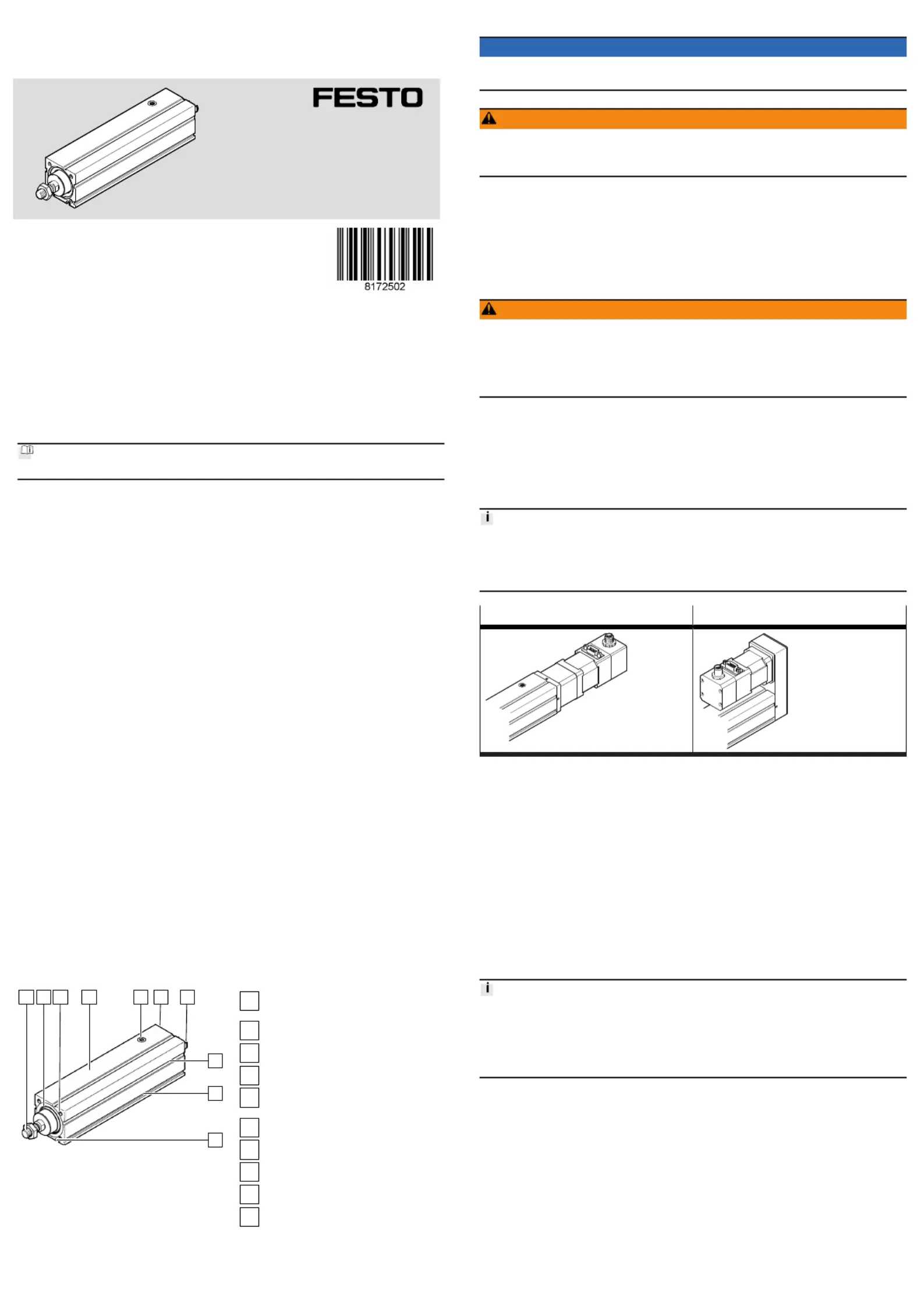
4.2 Product design
1 2 3 4 5 6 7
8
9
10
Fig. 1: Product design EPCC-BS,
example EPCC-BS-45-100-10P-
A7-A
1
Piston rod with male thread or female
thread
2
Guide ring with or without scraper
3
Threaded hole for mounting
4
Cylinder profile
5
Sealing air connection with filter ele-
ment
6
Interface for motor mounting kit
7
Drive hub
8
Slot for sensor bracket
9
Slot for profile mounting
10
Slot for slot nut
5 Transport
NOTICE
Unexpected and unbraked movement of components
Secure moving components for transport.
WARNING
Risk of injury due to falling product
If the product is lifted incorrectly, it may fall and cut, crush or separate body parts.
Lift the product only with suitable load-bearing equipment.
Store and transport the product in its original packaging. Observe the weight,
the dimensions and the ambient conditions.
Take the centre of gravity of the product into consideration.
Store and transport the product in a horizontal position.
6 Assembly
6.1 Safety
WARNING
Risk of Injury due to Unexpected Movement of Components
For vertical or slanted mounting position: when power is off, moving parts can
travel or fall uncontrolled into the lower end position.
Bring moving parts of the product into a safe end position or secure them
against falling.
6.2 Unpacking product
1. Open packaging.
2. Remove all transport materials, e.g. foils, caps, cardboard boxes.
3. Remove the product from the packaging and place it on the mounting surface.
4. Dispose of packaging and transport materials.
6.3 Mounting motor
Transverse load on the drive hub
When mounting the motor and motor mounting kit, do not exceed the maximum
transverse load FR of the drive hub, e.g. toothed belt tension when mounting the
parallel kit è 12.1 Technical data, mechanical.
Axial kit EAMM-A Parallel kit EAMM-U
Tab. 1: Overview of motor mountings
Requirement
Only loosen screws or threaded pins that are described in the directions in the
instruction manuals.
Sufficient space for reaching and mounting the sealing air connection .
1. Select the motor and motor mounting kit from
Festo
è www.festo.com/catalogue.
If other motors are used: observe the critical limits for forces, torques and
velocities.
2. Fasten motor mounting kit, observe instruction manual
è www.festo.com/sp.
3. Fasten the motor without tension. Support large and heavy motors.
Connect motor cables only on completion of mounting.
6.4 Mounting cylinder
High mechanical loads on the mounting connections
If high parallel torques are applied to the drive system at the same time, this will
result in high mechanical loads at the mounting interfaces.
If the mounting position is inclined or horizontal with direct fastening, the drive
system will require additional support near the motor mounting.
Requirement
No collision in the range of motion of the attachment component with motor,
mounting components and sensor components.
Sufficient space to reach maintenance interfaces.
Sufficient space for reaching and mounting the sealing air connection.
Flat mounting surface maximum 0.2 mm over the stroke length of the bearing
surface.
No distortion or bending when installing the product.
1. Select mounting attachments è www.festo.com/catalogue.
2. Place the mounting attachments on the support points.
3. Tighten retaining screws.
Observe the maximum tightening torque and screw-in depth.
For additional information, contact your local Festo Service.
Direct fastening Profile mounting
EAHF-L2
Flange mounting
EAHH
Swivel mounting
EAHS
Mounting via thread Mounting via profile
groove
Mounting via profile
groove
Mounting via profile
groove
Tab. 2: Overview of mounting components for profile
Adapter kit EAHA Swivel flange SNC...
Mounting via profile groove Mounting via thread (adapter kit EAHA)
Tab. 3: Overview of mounting components for parallel kit
Size 25 32 45 60
Direct fastening
Screw M4 M5 M6
Max. screw-in depth tmax [mm] – 8 10 12
Max. tightening torque [Nm] 3 4 5
Adapter kit EAHA
Flange mounting EAHH
Profile mounting EAHF-L2
Swivel mounting EAHS
Swivel flange SNC...
Screw Instruction manual è www.festo.com/sp
Tab. 4: Information for mounting components
6.5 Mounting attachment component
Torque on the Piston Rod
During commissioning and operation, the piston rod may only be operated
without torque.
If external torques occur, an external guide must be used.
Mounting the attachment component on the piston rod
When mounting the attachment component, do not exceed the maximum torque
of the piston rod. The maximum torque of the piston rod may only be used for a
short time during mounting è Tab. 7 Information on attachment components.
Collision-free Torque-free Guide load
Tab. 5: Requirement for attachment components
Requirement:
No collision in the range of motion of the attachment component with motor,
mounting components and sensor components.
No transverse load or torque on the piston rod.
Absorb external forces and torques by an external guide.
Minimise guide load. Short lever arms from the piston rod thread to the
force application points and centre of gravity of the add-on elements.
1. Select accessories è www.festo.com/catalogue.
2. Screw the lock nut onto the male thread of the piston rod or attachment
component.
3. Rotate or place the attachment component on the piston rod.
4. Tighten lock nut.
The tightening torque must not act on the piston rod. Counterhold with a
suitable tool on the spanner flat of the piston rod.
Observe maximum tightening torque.
Fig. 2: Torque-free mounting
When using an additional external guide, ensure that the electric cylinder and
piston rod are aligned exactly parallel.
EPCC-BS-... EPCC-BS-...-F
Mounting via male thread Mounting via female thread
with nut with screw
with lock nut
Rod eye SGS, CRSGS
Rod clevis SG, CRSG
Coupling piece KSG
Self-aligning rod coupler FK; CRFK
Tab. 6: Overview of attachment components
Size 25 32 45 60
Piston rod
Spanner size [mm] 7 9 10 13ß
Max. torque [Nm] 0.5 1 2 3
Piston rod with male thread EPCC-BS-...
Nut, lock nut M6 M8 M10x1.25 M12x1.25
Piston rod with female thread EPCC-BS-...-F
Screw, lock nut M4 M6 M8 M10
Max. screw-in depth tmax [mm] 10 12 14 16
Tab. 7: Information on attachment components
6.6 Mounting accessories
Requirement
No collision with mounting and sensor components in the movement space of
the attachment component.
Function
Protection against uncontrolled overtravel of the end positions.
Referencing to reference switch or end position.
Query of end positions or intermediate positions.
Prevention of hard impacts at the end positions.
Prevention of contamination in the slots.
1. Select accessories è www.festo.com/catalogue.
2. Mount the sensor (reference or query):
Mount sensor rail or mounting kit.
Align sensor and mount it at the switching position.
Fasten cable.
Instruction manuals è www.festo.com/sp.
Sensor bracket EAPM
Mounting via profile groove
Protect the sensor from external magnetic or
ferritic influences, e.g. min. 10 mm distance
to slot nuts.
Preferably use hardware limit switches with
N/C contact function to guarantee protection
in the event of a sensor failure.
Instruction manual è
www.festo.com/sp
Tab. 8: Overview of sensor mountings
Connecting sealing air
The use of sealing air at approx. ± 0.02 MPa (± 0.2 bar, ± 2.9 psi) reduces or
prevents subsequent contamination:
The application of negative pressure minimises the release of abraded particles
into the environment.
The application of overpressure reduces the penetration of dirt into the
drivetrain.
Fig. 3: Mounting fitting
1. Remove the filter element from the threaded hole.
2. Mount the screw fitting and connect the hose.
Size 25 32 45 60
Thread M5 M5 G1/8 G1/4
Max. screw-in depth [mm] 4 5 7 7
Max. tightening torque [Nm] 1.4 1.4 5 8
Tab. 9: Information on sealing air connection
7 Commissioning
7.1 Safety
WARNING
Risk of injury due to unexpected movement of components.
Protect the positioning range from unwanted intervention.
Keep foreign objects out of the positioning range.
Perform commissioning with low dynamic response.
7.2 Commissioning procedure
Block-shaped acceleration profiles without jerk limitation can have the following
effects:
High mechanical loads on the lead screw due to high force peaks.
Overshooting effects during positioning.
Rise of the entire system.
Recommendation: reduce high force peaks in the acceleration and deceleration
phases by using the jerk limitation.
When the motor is removed, the motor encoder loses its absolute reference to the
reference mark, e.g. by turning the motor drive shaft.
Carry out a homing run every time the motor is mounted in order to establish
the absolute reference between the motor encoder and the reference mark.
Torque on the Piston Rod
During commissioning and operation, the piston rod may only be operated
without torque.
If external torques occur, an external guide must be used.
Running noises during operation
Identically constructed axes can generate different running noises depending on
the parameterisation, mode of operation, type of mounting, installation environ-
ment and components.
For use with reduced particle emission
Clean product è 9.2 Cleaning.
Requirement
Mounting of the drive system is checked.
Installation and wiring of the motor is checked.
No foreign objects in the movement space of the drive system.
Maximum permissible feed force and drive torque not exceeded as a function
of acceleration, deceleration (e.g. stop function, quick stop), velocity, moving
mass and mounting position.
Cylinder not mechanically overloaded and dynamic setpoint deviation not
exceeded due to force peaks and torque peaks or overshoot effects, e.g. over-
running the end position.
Limit overloads and overruns by jerk limitation, reduced acceleration and decel-
eration setpoints or optimised controller settings.
Control run and homing with reduced setpoint values for speed, acceleration
and deceleration.
No test run to mechanical end stops.
Software end positions ≥ 0.25 mm away from the mechanical stops.
Steps Purpose Note
1. Check
travel
Determine the direc-
tion of travel of the
piston rod
Direction of movement of piston rod, clockwise spindle:
Retracting: rotate drive shaft clockwise.
Advancing: rotate drive shaft anti-clockwise.
The direction of movement of the piston rod for positive
and negative position values depends on the mounting
position of the motor on the cylinder, e.g. parallel or axial
kit.
Set a required reversal of direction of rotation via param-
eters in the servo drive or controller.
2. Homing Determination of
the reference point
and adjustment of
the dimensional ref-
erence system
during the initial
start-up proce-
dure
after replacement
of the motor
Permissible reference points:
towards reference switch:
Travel at reduced velocity è
12 Technical data.
towards end position:
do not exceed maximum values
è Tab. 11 Speed and
energy at the end positions.
Additional information Instruction manual of the driveè
system, è
www.festo.com/sp.
3. Test run Checking the oper-
ating conditions
Check application requirements:
Piston rod runs through the complete travel cycle in the
specified time.
The piston rod stops travel when a limit switch or soft-
ware end position is reached.
After a successful test run, the drive system is ready for operation.
Tab. 10: Commissioning steps
Size 25 32 45 60
Max. stop velocity [m/s] 0.01
Max. stop energy [mJ] 1.2 3.6 12 24
Calculation of the maximum stop energy
!" =#$%
2#&m#+#'(
')*
v = max. stop velocity
m = mass of all linear moving components
JR = mass moment of inertia of all rotating compo-
nents
JL = mass moment of inertia per kg payload
Additional information è
www.festo.com/catalogue.
Tab. 11: Speed and energy at the end positions
8 Operation
WARNING
Risk of injury due to unexpected movement of components.
Protect the positioning range from unwanted intervention.
Keep foreign objects out of the positioning range.
Perform commissioning with low dynamic response.
Torque on the Piston Rod
During commissioning and operation, the piston rod may only be operated
without torque.
If external torques occur, an external guide must be used.
Lubrication run during operation
Observe the following lubrication travel intervals.
With working stroke less than 2 x spindle pitch... P:
Perform a lubrication run within 10 travel cycles with a minimum stroke of
≥ 2 x spindle pitch.
9 Maintenance
9.1 Safety
WARNING
Unexpected movement of components.
Injury due to impacts or crushing.
Before working on the product, switch off the control and secure it to prevent it
from being switched back on accidentally.

Tuotetiedot

Merkki: Festo
Kategoria: Ei luokiteltu
Malli: EPCC-BS-60-400-5P-A

Tarvitsetko apua?

Jos tarvitset apua merkille Festo EPCC-BS-60-400-5P-A esitä kysymys alla ja muut käyttäjät vastaavat sinulle


Ei luokiteltu Festo Käyttöohjeet

Ei luokiteltu Käyttöohjeet

Viimeisimmät Ei luokiteltu Käyttöohjeet