Festo SFAB-1000U-WQ10-2SV-M12 Käyttöohje
Festo Ei luokiteltu SFAB-1000U-WQ10-2SV-M12
Lue alta 📖 käyttöohje suomeksi merkille Festo SFAB-1000U-WQ10-2SV-M12 (7 sivua) kategoriassa Ei luokiteltu. Tämä opas oli hyödyllinen 46 henkilölle ja sai 4.3 tähden keskimäärin 3 käyttäjältä
Sivu 1/7
SFAB
Flow sensor
Festo SE & Co. KG
Ruiter Straße 82
73734 Esslingen
Deutschland
+49 711 347-0
www.festo.com
Operating instructions
8156241
2021-05d
[8156243]
Translation of the original instructions
© 2021 all rights reserved to Festo SE & Co. KG
1
About this document
1.1
Applicable Documents
All available documents for the product
è
www.festo.com/sp.
2Safety
2.1
General safety instructions
–Only use the product in original status without unauthorised modifications.
–Only use the product if it is in perfect technical condition.
–
Observe labelling on the product.
–Condensation, oil mist, foreign matter and other contaminants in the com-
pressed air can damage the product. Only use media in accordance with the
specifications Technical data.è
–This product can generate high frequency malfunctions, which may make it nec-
essary to implement interference suppression measures in residential areas.
2.2Intended use
The SFAB is designed to monitor changes in the flow rate and air consumption of
gaseous media in piping systems or terminals in industry.
2.3Training of qualified personnel
Work on the product may only be carried out by qualified personnel who can
evaluate the work and detect dangers. The qualified personnel have skills and
experience in dealing with electropneumatic (open-loop) control technology.
2.4
Range of application and approvals
Certain configurations of the product have been certified by Underwriters Labora-
tories Inc. (UL) for the USA and Canada. These configurations bear the following
mark:
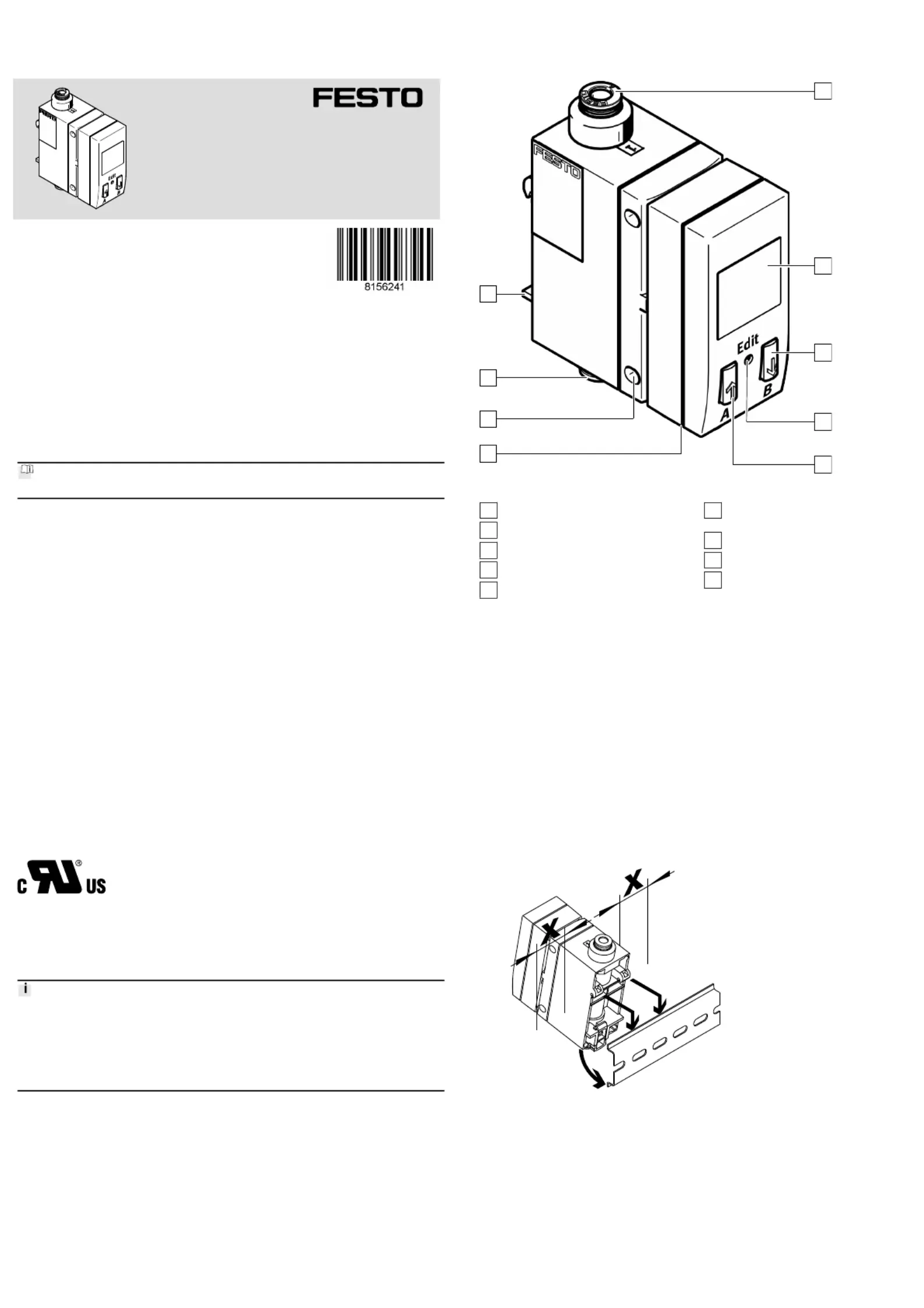
Fig.1
UL Recognized Component Mark for Canada and the United States. Only for
connection to an NEC Class 2 supply. Raccorder Uniquement a un circuit de Classe
2.
Observe the following if the UL requirements are to be complied with in your
application:
•Regulations for complying with the UL certification can be found in the sepa-
rate UL-specific special documentation. The technical data listed there take
priority.
•The technical data in this documentation may show values deviating from this.
3
Additional information
–Contact the regional Festo contact if you have technical problems
è
www.festo.com.
–Accessories and spare parts
è
www.festo.com/catalogue.
4
Product overview
4.1Product design
1
2
3
4
5
6
7
8
9
Fig. 2:SFAB
1
Supply port 1
2
Display
3
B pushbutton
4
Edit button
5
A pushbutton
6
Plug for the electrical connection
(M12)
7
Hole for plate mounting
8
Supply port 2
9
Mounting slide for H-rail and wall
mounting (rear)
4.2
Functional principle
The SFAB uses a thermal measurement method. Here, the amount of heat drawn
from a heated surface of the sensor by the medium flowing past it is calculated.
Through the amount of heat removed, the flow rate or accumulated air consump-
tion is determined and shown on the display. The connection to higher-level
systems is implemented through 2 binary outputs (Out A/OutB) and one analogue
output. Switching points can be defined for both binary outputs. Switching points
for both binary outputs are possible for flow rate measurement, a consumption
switching pulse for output A (OutA) is possible for cumulative air consumption
measurement. The combination of cumulative air consumption measurement
(OutA) and flow rate measurement (OutB) is possible. The flow value is output
via the analogue output.
5Assembly
5.1H-rail (manifold assembly)
1.
Maintain lateral distance x = 10 mm to earthed surfaces.
2.
Hang SFAB in H-rail.
3.Press SFAB in the direction of the arrow.
Ä
SFAB snaps into place.
5.2Wall mounting
1.
Maintain lateral distance x = mm to earthed surfaces.
Tuotetiedot
| Merkki: | Festo |
| Kategoria: | Ei luokiteltu |
| Malli: | SFAB-1000U-WQ10-2SV-M12 |
Tarvitsetko apua?
Jos tarvitset apua merkille Festo SFAB-1000U-WQ10-2SV-M12 esitä kysymys alla ja muut käyttäjät vastaavat sinulle
Ei luokiteltu Festo Käyttöohjeet

30 Maaliskuuta 2025
30 Maaliskuuta 2025
30 Maaliskuuta 2025
30 Maaliskuuta 2025
30 Maaliskuuta 2025
30 Maaliskuuta 2025
30 Maaliskuuta 2025
30 Maaliskuuta 2025
30 Maaliskuuta 2025
30 Maaliskuuta 2025
Ei luokiteltu Käyttöohjeet
Viimeisimmät Ei luokiteltu Käyttöohjeet
9 Huhtikuuta 2025
9 Huhtikuuta 2025
9 Huhtikuuta 2025
9 Huhtikuuta 2025
9 Huhtikuuta 2025
9 Huhtikuuta 2025
9 Huhtikuuta 2025
9 Huhtikuuta 2025
9 Huhtikuuta 2025
9 Huhtikuuta 2025