Festo VOFC-LT-M32C Käyttöohje
Festo
Ei luokiteltu
VOFC-LT-M32C
Lue alta 📖 käyttöohje suomeksi merkille Festo VOFC-LT-M32C (2 sivua) kategoriassa Ei luokiteltu. Tämä opas oli hyödyllinen 17 henkilölle ja sai 4.5 tähden keskimäärin 2 käyttäjältä
Sivu 1/2
VOFC-LT-M32C
Valve
Festo SE & Co. KG
Ruiter Straße 82
73734 Esslingen
Germany
+49 711 347-0
www.festo.com
Operating instruction
8115806
2023-02a
[8101559]
8115806
Translation of the original instructions
© 2023 all rights reserved to Festo SE & Co. KG
1 About this document
1.1 Purpose of the document
This document describes the use of the above-mentioned product. It contains
additional information for the use of the product in safety-related systems (safety
manual in accordance with IEC61508).
1.2 Applicable documents
–Assembly instructions
All available documents for the product
èwww.festo.com/sp.
1.3 Target group
This document is targeted towards individuals who mount and operate the
product. It is additionally targeted towards individuals who are entrusted with
the planning and application of the product in a safety-oriented system.
1.4 Specified standards
Version
IEC 61508-1:2010 IEC 61508-4:2010
IEC 61508-2:2010 IEC 61511:2016
Tab. 1: Specified standards
2 Safety
2.1 Safety instructions
–Only use the product in its original condition without unauthorised modifica-
tions.
–Only use the product if it is in perfect technical condition.
–Observe the identifications on the product.
–Only use media in accordance with the specifications è10Technical data.
–The product must be regularly tested by a qualified technician, and the test
must be documented è9Maintenance.
Return to Festo
–In the event of malfunctions or failure: replace the product and inform Festo of
the failure.
–Before returning the product, contact your Festo specialist advisor.
2.2 Intended use
The valves VOFC-LT-M32C are directly actuated electromechanical control valves.
The consist of a basic valve of the VOFC-LT-M32C series in combination with a
solenoid coil of the VACC-S13 series. The valves are used to control pneumatic
actuators.
2.3 Training of qualified personnel
Work on the product may only be carried out by qualified personnel who can
evaluate the work and detect dangers. The qualified personnel have knowledge
and experience in process automation.
3 Additional information
–Contact the regional Festo contact if you have technical problems
èwww.festo.com.
–Accessories and spare parts èwww.festo.com/catalogue.
4 Information on functional safety
4.1 Achievable safety classification
The product is suitable for use as an element in a safety-oriented system in
accordance with IEC 61511.
–in low-demand mode up to SIL 2
–in high-demand mode up to SIL 2.
Taking into account the necessary minimum hardware fault tolerance of HFT = 1,
the product can also be used up to SIL 3 with a redundant design of the entire
system.
NOTICE
It is only possible to determine whether the product is suitable for specific appli-
cations by also assessing further components of the subsystem.
4.2 Safety function
The safety function comprises the safe venting of an actuator connected to port 2.
The safety function is triggered by switching off the power supply at the solenoid
coil.
The connection between ports 2 and 3 remains open while the voltage remains
switched off at the solenoid coil. This switching position represents the safe state.
4.3 Operating conditions
–General information on safe operation
è2Safety.
–Periodic tests (performance test) è9Maintenance.
–Ambient conditions and additional technical specifications è10Technical
data.
4.4 Limitations of use
If the operating conditions are in compliance, the service life is a maximum of
14years.
5 Function
The valve is a 3/2-way valve with internal pilot air supply. If the operating pressure
is less than 2bar, an external pilot air supply with 2 bar must be connected.>
When the system is de-energised, the armature is pressed onto the nozzle by a
spring. This closes the internal pilot air line leading to the diaphragm.
–If voltage is applied at the solenoid coil: the armature opens the nozzle. The
diaphragm pushes the control piston against a spring in the final control ele-
ment. Exhaust port3 is closed and the flow rate between ports 1 and 2 is
unblocked.
–If there is no voltage at the solenoid coil: the compressed air supply from port1
is closed. Port 2is connected with exhaust port3. This allows a downstream
control unit to be exhausted.
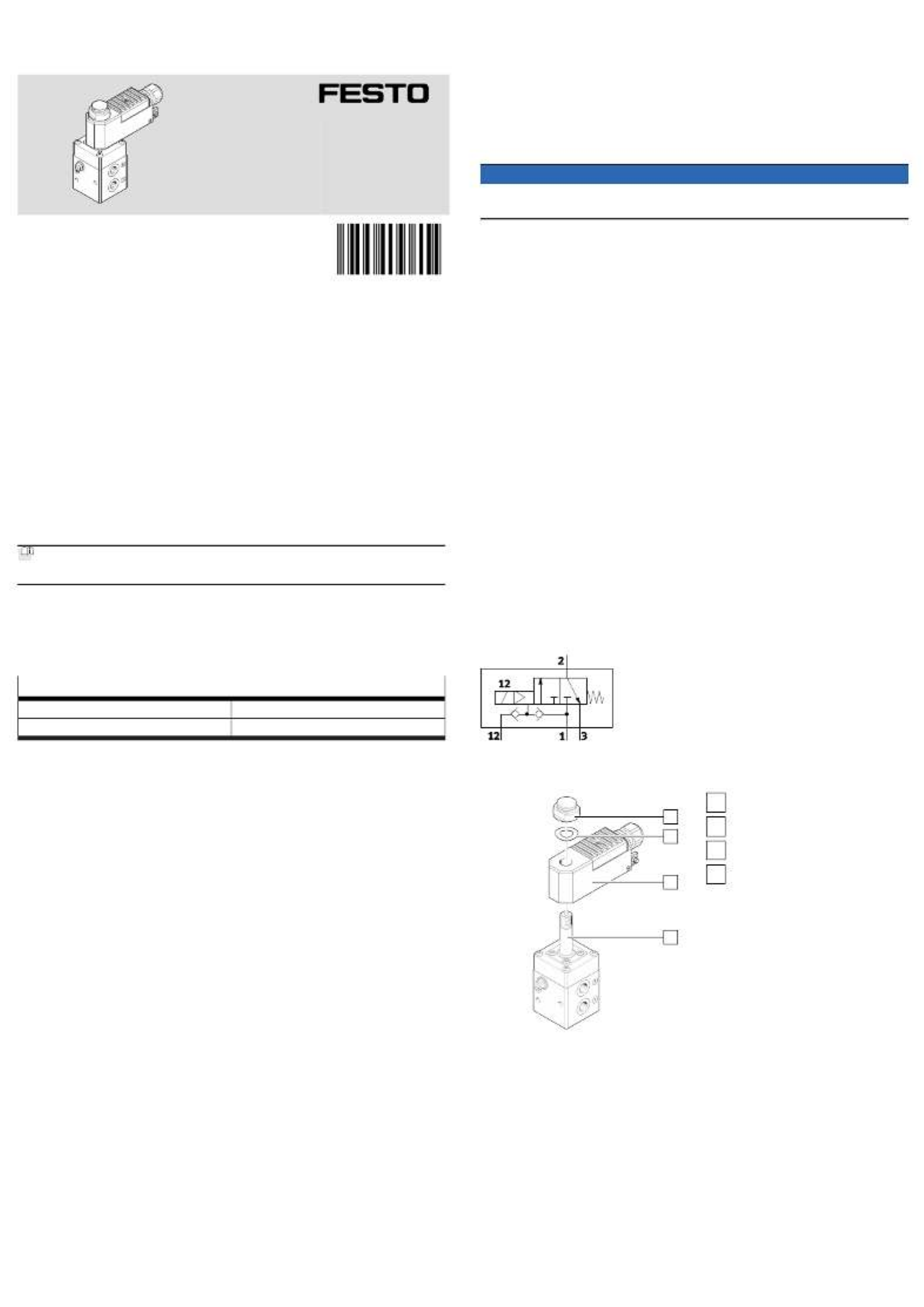
Fig. 1: Circuit symbol
6 Assembly
1
2
3
4
Fig. 2: Mounting the solenoid coil on
the valve body
1
Vent screw
2
Spring washer
3
Solenoid coil
4
Armature guide tube
1. Ensure that moisture cannot accumulate in the valve.
2. Slide solenoid coil [3] onto the armature guide tube [4]. Check: sealing com-
pound points to the valve body.
3. Slide spring washer [2] onto the armature guide tube.
4. Tighten vent screw [1]. Tightening torque: 5Nm ±20%.
7 Installation
7.1 Requirements
–The piping is unpressurised.
–Connecting cables and fittings are clean.
–The power supply is switched off.
5.
6.
7.2 Pneumatic installation
–Recommended: use feed line with 6 mm cross-section.³
–Use only fittings with cylindrical threaded stud and sealing ring or cutting ring.
–Do not use additional sealing agents such as PTFE sealing band or hemp.
–Do not use anti-friction coating or lubricant.
–If port1 is pressurised with a 2bar control signal, supply 2bar auxiliary< >
energy to port12.
For outdoor applications
NOTICE
Moisture, foreign matter and other contamination that enters the valve can
damage the product and affect its function.
• Ensure that there is ventilation.
• Use exhaust protection.
–Duct exhaust air
–Use exhaust protection VABD-D3-….
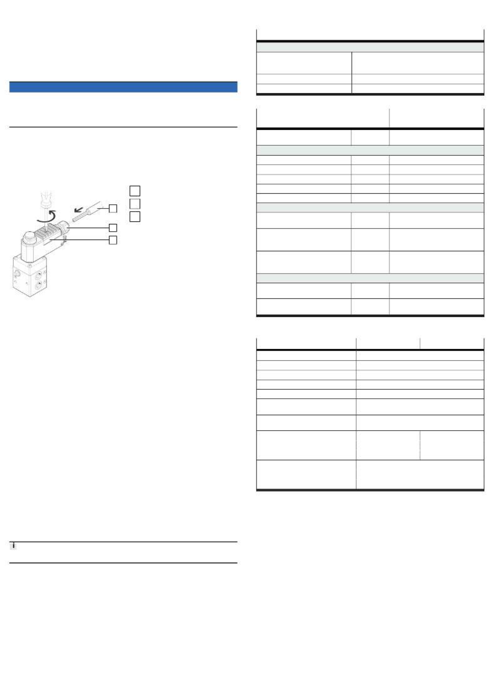
7.3 Electrical installation
–Take suitable measures for the protective circuit to limit peak disconnection
voltages.
–Any polarity.
1
2
3
Fig. 3: Electrical connection of
solenoid coil
1
Cable
2
Cable fitting
3
Cover
1. Loosen the screw of the terminal housing and open the cover [3].
2. When loosening the cap nut of the cable fitting [2] hold the lock nut on the
housing in position to prevent it from loosening (use second spanner).
3. Guide the cable [1] through the cable fitting and wire it to the terminals.
4. Connect the solenoid coil to the local equipotential bonding via the inner or
outer protective earth connection.
Tighten the cap nut of the cable fitting [2].
–Tightening torque: 4.3 Nm ± 10%
Close the cover [3] of the terminal housing and tighten the screw.
–Tightening torque: 1.2 Nm ± 20%
7. Functional test: operate the solenoid valve a few times and check that it
functions correctly.
8 Commissioning
• After complete assembly and installation, check and document the safety
function.
9 Maintenance
9.1 General
–When used as intended, the product is maintenance-free.
–Repairs to the product are not permissible. In the event of malfunctions or
failure: Replace the product and let Festo know about the failure. Return defec-
tive products to Festo.
9.2 Proof test (Proof test)
The proof test consists of switching off the voltage at the solenoid valve and then
switching it on again.
During the proof test, the safety of the application must be ensured.
1. Switch off the voltage at the solenoid coil.
2. Measure the time until the pressure at port2 has completely reached the
ambient pressure (reached the safe state).
ÄThe test is successful if the safe state is reached within the given time
and a downstream final control element has moved to its intended posi-
tion.
3. Switch on the voltage at the solenoid coil.
ÄThe test is successful if the pressure at port2 has reached the original
value.
4. Check the valve externally, visual inspection.
ÄThe test is successful if no defect, leakage or contamination is detected.
5. Document the test results.
10 Technical data
10.1 Technical data, safety engineering
Approval information, safety engineering
CE
Type-examination The functional safety engineering of the product has been
certified by an independent testing body, see EC-type
examination certificate èwww.festo.com/sp
Certificate issuing authority TÜV Rheinland Industrie Service GmbH
Certificate no. 968/V 1251.00/21
Tab. 2: Approval information, safety engineering
Safety characteristic in accordance with IEC
61508
Value
Safety function Moving to the safe position by switching
off the power supply
Results of Assessment
Route of Assessment 2H/1S
Type of Subsystem Type A
Mode of Operation Low Demand Mode/High Demand Mode
Hardware Fault Tolerance HFT 0
Systematic Capability SC 3
Low Demand Mode
Dangerous Failure Rate ëD1.18 * 10-7/h
118 FIT
Average Probability of Failure on Demand
1oo1
PFD
avg(T1) 5.25 * 10-4
Assumptions: DC = 0%, T1= 1 year,
MRT = 72 h
Average Probability of Failure on Demand
1oo2
PFD
avg(T1) 5.28 * 10-5
Assumptions: DC = 0%, T1= 1 year,
MRT = 72 h, ß
1oo2 = 10%
High Demand Mode
Nominal Lifetime in accordance with
EN13611:2007+A2:2011K.4.6
B
10d 1,478,101
Average Frequency of a Dangerous
Failure per Hour
PFH 6.8 * 10
-8/h
Tab. 3: Safety characteristics
10.2 Technical data, general
VOFC-LT-M32C-… -…14 -…12
Mounting position any
Medium Compressed air to ISO 8573-1:2010[7:2:2]
Temperature of medium [°C] –25…60
Ambient temperature [°C] –25…60
Storage temperature [°C] –20…40
Corrosion resistance class
CRC
4
Degree of protection (in
mounted state)
IP65
Operating pressure [MPa] 0.1…0.8 0.2…0.8
[bar] 1…8 2…8
[psi] 14.5…116 29…116
Operating pressure with
external pilot air
[MPa] 0…0.8
[bar] 0…8
[psi] 0…116
Tab. 4: Technical data
Tuotetiedot
| Merkki: | Festo |
| Kategoria: | Ei luokiteltu |
| Malli: | VOFC-LT-M32C |
Tarvitsetko apua?
Jos tarvitset apua merkille Festo VOFC-LT-M32C esitä kysymys alla ja muut käyttäjät vastaavat sinulle
Ei luokiteltu Festo Käyttöohjeet

30 Maaliskuuta 2025
30 Maaliskuuta 2025
30 Maaliskuuta 2025
30 Maaliskuuta 2025
30 Maaliskuuta 2025
30 Maaliskuuta 2025
30 Maaliskuuta 2025
30 Maaliskuuta 2025
30 Maaliskuuta 2025
30 Maaliskuuta 2025
Ei luokiteltu Käyttöohjeet
- Ei luokiteltu MSW
- Ei luokiteltu Stamos
- Ei luokiteltu Teka
- Ei luokiteltu Ulsonix
- Ei luokiteltu Aiwa
- Ei luokiteltu Maytag
- Ei luokiteltu Stamony
- Ei luokiteltu Laica
- Ei luokiteltu Thomson
- Ei luokiteltu Amana
- Ei luokiteltu Uniprodo
- Ei luokiteltu Miele
- Ei luokiteltu Whirlpool
- Ei luokiteltu ORNO
- Ei luokiteltu Ledlenser
- Ei luokiteltu Fujifilm
- Ei luokiteltu Etna
- Ei luokiteltu Haier
- Ei luokiteltu KitchenAid
- Ei luokiteltu Bauhn
- Ei luokiteltu Insignia
- Ei luokiteltu Royal Catering
- Ei luokiteltu LG
- Ei luokiteltu Bosch
- Ei luokiteltu Jocel
- Ei luokiteltu Power Dynamics
- Ei luokiteltu BEKO
- Ei luokiteltu Exquisit
- Ei luokiteltu Grundig
- Ei luokiteltu Hisense
- Ei luokiteltu Sharp
- Ei luokiteltu D-Link
- Ei luokiteltu Boneco
- Ei luokiteltu Electrolux
- Ei luokiteltu Apc
- Ei luokiteltu Severin
- Ei luokiteltu Café
- Ei luokiteltu Balay
- Ei luokiteltu DeWalt
- Ei luokiteltu Siemens
- Ei luokiteltu Hama
- Ei luokiteltu Petsafe
- Ei luokiteltu Vorago
- Ei luokiteltu Neewer
- Ei luokiteltu Jensen
- Ei luokiteltu Danby
- Ei luokiteltu Bartscher
- Ei luokiteltu Hartke
- Ei luokiteltu Gigabyte
- Ei luokiteltu Smeg
- Ei luokiteltu Gree
- Ei luokiteltu Hoover
- Ei luokiteltu EBERLE
- Ei luokiteltu Hazet
- Ei luokiteltu Fluke
- Ei luokiteltu Philips
- Ei luokiteltu Goobay
- Ei luokiteltu Topeak
- Ei luokiteltu Antari
- Ei luokiteltu Thermex
- Ei luokiteltu TCL
- Ei luokiteltu Russell Hobbs
- Ei luokiteltu Panduit
- Ei luokiteltu IFM
- Ei luokiteltu Avantree
- Ei luokiteltu Hotpoint
- Ei luokiteltu Schwaiger
- Ei luokiteltu Nabo
- Ei luokiteltu Arendo
- Ei luokiteltu Godox
- Ei luokiteltu Megger
- Ei luokiteltu Balam Rush
- Ei luokiteltu Noxon
- Ei luokiteltu Amica
- Ei luokiteltu Sanus
- Ei luokiteltu Adidas
- Ei luokiteltu Domo
- Ei luokiteltu IKEA
- Ei luokiteltu Cayin
- Ei luokiteltu AEG
- Ei luokiteltu Reflexion
- Ei luokiteltu TP Link
- Ei luokiteltu Inventum
- Ei luokiteltu Totolink
- Ei luokiteltu Shokz
- Ei luokiteltu Gamma
- Ei luokiteltu Medel
- Ei luokiteltu Meris
- Ei luokiteltu Navitel
- Ei luokiteltu Meridian
- Ei luokiteltu Cecotec
- Ei luokiteltu AeroCool
- Ei luokiteltu Kugoo
- Ei luokiteltu Rikon
- Ei luokiteltu Samsung
- Ei luokiteltu Neff
- Ei luokiteltu Garmin
- Ei luokiteltu Razer
- Ei luokiteltu Teufel
- Ei luokiteltu Enermax
- Ei luokiteltu Noveen
- Ei luokiteltu Fender
- Ei luokiteltu StarTech.com
- Ei luokiteltu Origin Storage
- Ei luokiteltu Outwell
- Ei luokiteltu Best
- Ei luokiteltu Stihl
- Ei luokiteltu Delonghi
- Ei luokiteltu Kostal
- Ei luokiteltu ZOTAC
- Ei luokiteltu Comfee
- Ei luokiteltu Imarflex
- Ei luokiteltu Edgestar
- Ei luokiteltu Audient
- Ei luokiteltu Kogan
- Ei luokiteltu Solis
- Ei luokiteltu DJI
- Ei luokiteltu Snom
- Ei luokiteltu McIntosh
- Ei luokiteltu One For All
- Ei luokiteltu Caple
- Ei luokiteltu SereneLife
- Ei luokiteltu Turbosound
- Ei luokiteltu Behringer
- Ei luokiteltu Roesle
- Ei luokiteltu APSystems
- Ei luokiteltu Sony
- Ei luokiteltu GoGEN
- Ei luokiteltu Nitecore
- Ei luokiteltu Create
- Ei luokiteltu Furrion
- Ei luokiteltu Oreg
- Ei luokiteltu Glorious
- Ei luokiteltu Pro-Ject
- Ei luokiteltu Yamaha
- Ei luokiteltu CaviLock
- Ei luokiteltu OOONO
- Ei luokiteltu Xiaomi
- Ei luokiteltu Venom
- Ei luokiteltu Morel
- Ei luokiteltu Kichler
- Ei luokiteltu Topex
- Ei luokiteltu SMART Technologies
- Ei luokiteltu Trust
- Ei luokiteltu Neo
- Ei luokiteltu Morphy Richards
- Ei luokiteltu Newstar
- Ei luokiteltu Legrand
- Ei luokiteltu Integral LED
- Ei luokiteltu Goodram
- Ei luokiteltu Goldtouch
- Ei luokiteltu Lutec
- Ei luokiteltu Vello
- Ei luokiteltu Asus
- Ei luokiteltu Cudy
- Ei luokiteltu Midea
- Ei luokiteltu SBS
- Ei luokiteltu Hayter
- Ei luokiteltu BlueBuilt
- Ei luokiteltu Eufy
- Ei luokiteltu Gys
- Ei luokiteltu Conair
- Ei luokiteltu Franke
- Ei luokiteltu Husqvarna
- Ei luokiteltu Sauber
- Ei luokiteltu Candy
- Ei luokiteltu Shimano
- Ei luokiteltu Axis
- Ei luokiteltu Tamron
- Ei luokiteltu Liebherr
- Ei luokiteltu Carson
- Ei luokiteltu Gourmetmaxx
- Ei luokiteltu Viking
- Ei luokiteltu Gembird
- Ei luokiteltu Truelife
- Ei luokiteltu AkYtec
- Ei luokiteltu Busch-Jaeger
- Ei luokiteltu ETA
- Ei luokiteltu Voltcraft
- Ei luokiteltu Axor
- Ei luokiteltu Duravit
- Ei luokiteltu Karran
- Ei luokiteltu Elkay
- Ei luokiteltu Brennenstuhl
- Ei luokiteltu Extron
- Ei luokiteltu My Wall
- Ei luokiteltu Lindy
- Ei luokiteltu HP
- Ei luokiteltu HiLook
- Ei luokiteltu Aputure
- Ei luokiteltu Netgear
- Ei luokiteltu BaByliss
- Ei luokiteltu Honor
- Ei luokiteltu XP-PEN
- Ei luokiteltu Danfoss
- Ei luokiteltu Riccar
- Ei luokiteltu Orbegozo
- Ei luokiteltu Media-tech
- Ei luokiteltu Kuppersbusch
- Ei luokiteltu BOYA
- Ei luokiteltu Mebby
- Ei luokiteltu Pioneer
- Ei luokiteltu NEO Tools
- Ei luokiteltu TONI&GUY
- Ei luokiteltu Gorenje
- Ei luokiteltu Summit
- Ei luokiteltu Accucold
- Ei luokiteltu EarFun
- Ei luokiteltu Toolcraft
- Ei luokiteltu Gram
- Ei luokiteltu WarmlyYours
- Ei luokiteltu Gemini
- Ei luokiteltu Somfy
- Ei luokiteltu Lorex
- Ei luokiteltu Catit
- Ei luokiteltu NuPrime
- Ei luokiteltu Ecler
- Ei luokiteltu Roccat
- Ei luokiteltu AudioControl
- Ei luokiteltu Elsner
- Ei luokiteltu Kask
- Ei luokiteltu Digitus
- Ei luokiteltu Stokke
- Ei luokiteltu Cabasse
- Ei luokiteltu Koenic
- Ei luokiteltu Panasonic
- Ei luokiteltu Beaphar
- Ei luokiteltu Sure Petcare
- Ei luokiteltu Rotel
- Ei luokiteltu Livall
- Ei luokiteltu KEF
- Ei luokiteltu Monogram
- Ei luokiteltu Sortimo
- Ei luokiteltu Unicol
- Ei luokiteltu Audio-Technica
- Ei luokiteltu Olimpia Splendid
- Ei luokiteltu Lian Li
- Ei luokiteltu JLab
- Ei luokiteltu Toa
- Ei luokiteltu Marantz
- Ei luokiteltu Knog
- Ei luokiteltu Rega
- Ei luokiteltu Vox
- Ei luokiteltu Mars Gaming
- Ei luokiteltu Kerbl
- Ei luokiteltu Metra
- Ei luokiteltu Pyle
- Ei luokiteltu Westinghouse
- Ei luokiteltu Sencor
- Ei luokiteltu Cello
- Ei luokiteltu Hobby
- Ei luokiteltu Lenovo
- Ei luokiteltu Medion
- Ei luokiteltu Noctua
- Ei luokiteltu Klein Tools
- Ei luokiteltu LevelOne
- Ei luokiteltu Shure
- Ei luokiteltu Michael Todd Beauty
- Ei luokiteltu GRAUGEAR
- Ei luokiteltu Trixie
- Ei luokiteltu Schneider
- Ei luokiteltu Lorelli
- Ei luokiteltu Roland
- Ei luokiteltu OBSBOT
- Ei luokiteltu Epson
- Ei luokiteltu SuperTooth
- Ei luokiteltu Kluge
- Ei luokiteltu Bobrick
- Ei luokiteltu Signature Hardware
- Ei luokiteltu Martin
- Ei luokiteltu Kanto
- Ei luokiteltu Scott
- Ei luokiteltu Delta
- Ei luokiteltu Kindermann
- Ei luokiteltu Robern
- Ei luokiteltu Hortus
- Ei luokiteltu DeLock
- Ei luokiteltu Bertazzoni
- Ei luokiteltu Coyote
- Ei luokiteltu Kidde
- Ei luokiteltu Anker
- Ei luokiteltu Growatt
- Ei luokiteltu Nanoleaf
- Ei luokiteltu Stirling
- Ei luokiteltu Mistral
- Ei luokiteltu JVC
- Ei luokiteltu VMV
- Ei luokiteltu S.M.S.L
- Ei luokiteltu Privileg
- Ei luokiteltu MPM
- Ei luokiteltu Niceboy
- Ei luokiteltu Engenius
- Ei luokiteltu Khind
- Ei luokiteltu Motorola
- Ei luokiteltu EMOS
- Ei luokiteltu CyberPower
- Ei luokiteltu Sharper Image
- Ei luokiteltu RGBlink
- Ei luokiteltu Clean Air Optima
- Ei luokiteltu Manfrotto
- Ei luokiteltu Cosatto
- Ei luokiteltu Lego
- Ei luokiteltu Fluval
- Ei luokiteltu Cleco
- Ei luokiteltu Kicker
- Ei luokiteltu Bauknecht
- Ei luokiteltu Gude
- Ei luokiteltu Auna
- Ei luokiteltu Taurus
- Ei luokiteltu Heatit
- Ei luokiteltu Midland
- Ei luokiteltu Field Optics
- Ei luokiteltu Zebra
- Ei luokiteltu Yealink
- Ei luokiteltu FIMI
- Ei luokiteltu Optex
- Ei luokiteltu Frigidaire
- Ei luokiteltu Levoit
- Ei luokiteltu Deye
- Ei luokiteltu Dimplex
- Ei luokiteltu OSD Audio
- Ei luokiteltu Nibe
- Ei luokiteltu Ryobi
- Ei luokiteltu Dremel
- Ei luokiteltu Breville
- Ei luokiteltu Kodak
- Ei luokiteltu Velleman
- Ei luokiteltu Sharkoon
- Ei luokiteltu Laserliner
- Ei luokiteltu Segway
- Ei luokiteltu Cameo
- Ei luokiteltu Casio
- Ei luokiteltu DataVideo
- Ei luokiteltu RGV
- Ei luokiteltu Hendi
- Ei luokiteltu Gamdias
- Ei luokiteltu Concept
- Ei luokiteltu BeamZ
- Ei luokiteltu Livoo
- Ei luokiteltu Nexa
- Ei luokiteltu Guzzanti
- Ei luokiteltu XO
- Ei luokiteltu Steinel
- Ei luokiteltu Bluesound
- Ei luokiteltu Flex
- Ei luokiteltu Chauvin Arnoux
- Ei luokiteltu Blackstar
- Ei luokiteltu Caso
- Ei luokiteltu Hertz
- Ei luokiteltu Kenwood
- Ei luokiteltu Cambridge
- Ei luokiteltu Nobo
- Ei luokiteltu Dell
- Ei luokiteltu Ciarra
- Ei luokiteltu Brandson
- Ei luokiteltu Mybeo
- Ei luokiteltu Aplic
- Ei luokiteltu CSL
- Ei luokiteltu Zoom
- Ei luokiteltu Tru Components
- Ei luokiteltu Hitachi
- Ei luokiteltu Fisher Paykel
- Ei luokiteltu Bearware
- Ei luokiteltu Moen
- Ei luokiteltu Fulgor Milano
- Ei luokiteltu Viewsonic
- Ei luokiteltu B-tech
- Ei luokiteltu Hyundai
- Ei luokiteltu IMM Photonics
- Ei luokiteltu Hansgrohe
- Ei luokiteltu Maginon
- Ei luokiteltu Speco Technologies
- Ei luokiteltu Nec
- Ei luokiteltu IFi Audio
- Ei luokiteltu Tripp Lite
- Ei luokiteltu Nevir
- Ei luokiteltu Infiniton
- Ei luokiteltu Sennheiser
- Ei luokiteltu Ag Neovo
- Ei luokiteltu Henry Engineering
- Ei luokiteltu Taco Tuesday
- Ei luokiteltu Wire Technologies
- Ei luokiteltu GPO
- Ei luokiteltu Block
- Ei luokiteltu Maxi-Cosi
- Ei luokiteltu Ufesa
- Ei luokiteltu Milwaukee
- Ei luokiteltu Smart-AVI
- Ei luokiteltu CEEM
- Ei luokiteltu CAME-TV
- Ei luokiteltu A-Designs
- Ei luokiteltu EchoMaster
- Ei luokiteltu Krups
- Ei luokiteltu Crimson
- Ei luokiteltu Elgato
- Ei luokiteltu Corsair
- Ei luokiteltu Generac
- Ei luokiteltu EVE
- Ei luokiteltu Dahua Technology
- Ei luokiteltu Cambium Networks
- Ei luokiteltu Safety 1st
- Ei luokiteltu Scarlett
- Ei luokiteltu Axxess
- Ei luokiteltu Advance
- Ei luokiteltu Indesit
- Ei luokiteltu Daikin
- Ei luokiteltu Shoprider
- Ei luokiteltu Canon
- Ei luokiteltu Rowenta
- Ei luokiteltu VAIS Technology
- Ei luokiteltu Zephyr
- Ei luokiteltu Maxsa
- Ei luokiteltu Kern
- Ei luokiteltu Lincoln Electric
- Ei luokiteltu BRIO
- Ei luokiteltu Taylor
- Ei luokiteltu AXESS
- Ei luokiteltu DAB
- Ei luokiteltu Be Cool
- Ei luokiteltu Bluetti
- Ei luokiteltu Blaupunkt
- Ei luokiteltu Thermaltake
- Ei luokiteltu Artsound
- Ei luokiteltu Simrad
- Ei luokiteltu Volcano
- Ei luokiteltu Nordic Winter
- Ei luokiteltu TechBite
- Ei luokiteltu Master
- Ei luokiteltu NEP
- Ei luokiteltu Catlink
- Ei luokiteltu Cablexpert
- Ei luokiteltu Ansmann
- Ei luokiteltu Røde
- Ei luokiteltu Makita
- Ei luokiteltu Einhell
- Ei luokiteltu Elac
- Ei luokiteltu Lewitt
- Ei luokiteltu Anova
- Ei luokiteltu Posiflex
- Ei luokiteltu Planet
- Ei luokiteltu Biostar
- Ei luokiteltu Mitsubishi
- Ei luokiteltu HeadRush
- Ei luokiteltu Marshall
- Ei luokiteltu Showtec
- Ei luokiteltu PCE
- Ei luokiteltu Hikvision
- Ei luokiteltu Sitecom
- Ei luokiteltu Navman
- Ei luokiteltu JIMMY
- Ei luokiteltu Equip
- Ei luokiteltu Conceptronic
- Ei luokiteltu Sirius
- Ei luokiteltu Noyafa
- Ei luokiteltu Yorkville
- Ei luokiteltu Toro
- Ei luokiteltu Intermatic
- Ei luokiteltu Spear & Jackson
- Ei luokiteltu Tower
- Ei luokiteltu Hubble Connected
- Ei luokiteltu McGregor
- Ei luokiteltu Habitat
- Ei luokiteltu MSR
- Ei luokiteltu Entes
- Ei luokiteltu V-Tac
- Ei luokiteltu Salton
- Ei luokiteltu Novation
- Ei luokiteltu Chipolino
- Ei luokiteltu Alphatronics
- Ei luokiteltu Fezz
- Ei luokiteltu Eden
- Ei luokiteltu Fuxtec
- Ei luokiteltu Graef
- Ei luokiteltu Megasat
- Ei luokiteltu SolaX Power
- Ei luokiteltu Valcom
- Ei luokiteltu Mikrotik
- Ei luokiteltu Yale
- Ei luokiteltu Mosconi
- Ei luokiteltu Kohler
- Ei luokiteltu Envertec
- Ei luokiteltu Celly
- Ei luokiteltu Metabo
- Ei luokiteltu Jabra
- Ei luokiteltu Alphacool
- Ei luokiteltu Belanger
- Ei luokiteltu Cuisinart
- Ei luokiteltu Doepke
- Ei luokiteltu Lupine
- Ei luokiteltu Anton/Bauer
- Ei luokiteltu Acer
- Ei luokiteltu Dometic
- Ei luokiteltu JBL
- Ei luokiteltu Rigol
- Ei luokiteltu Joy-it
- Ei luokiteltu Body Solid
- Ei luokiteltu Infinity
- Ei luokiteltu DeepCool
- Ei luokiteltu Kali Audio
- Ei luokiteltu Chief
- Ei luokiteltu Majority
- Ei luokiteltu Cybex
- Ei luokiteltu Iiyama
- Ei luokiteltu Nedis
- Ei luokiteltu Crock-Pot
- Ei luokiteltu Helix
- Ei luokiteltu Genesis
- Ei luokiteltu Dyson
- Ei luokiteltu SKS
- Ei luokiteltu Elation
- Ei luokiteltu Magmatic
- Ei luokiteltu Supermicro
- Ei luokiteltu Zendure
- Ei luokiteltu Logilink
- Ei luokiteltu Majestic
- Ei luokiteltu Basetech
- Ei luokiteltu Leviton
- Ei luokiteltu Soundstream
- Ei luokiteltu Klipsch
- Ei luokiteltu PAC
- Ei luokiteltu Xaoc
- Ei luokiteltu Eldom
- Ei luokiteltu Fisher And Paykel
- Ei luokiteltu Hohner
- Ei luokiteltu Britax
- Ei luokiteltu Elba
- Ei luokiteltu Steiner
- Ei luokiteltu Vonroc
- Ei luokiteltu Worx
- Ei luokiteltu Brentwood
- Ei luokiteltu Philco
- Ei luokiteltu Bellari
- Ei luokiteltu Gossen Metrawatt
- Ei luokiteltu Rolls
- Ei luokiteltu MSI
- Ei luokiteltu Chauvet
- Ei luokiteltu Ordo
- Ei luokiteltu Ground Zero
- Ei luokiteltu OnePlus
- Ei luokiteltu V7
- Ei luokiteltu Jenn-Air
- Ei luokiteltu CRUX
- Ei luokiteltu Karma
- Ei luokiteltu Ridem
- Ei luokiteltu Glemm
- Ei luokiteltu StarIink
- Ei luokiteltu Prixton
- Ei luokiteltu HomeCraft
- Ei luokiteltu Nostalgia
- Ei luokiteltu GameDay
- Ei luokiteltu X-Lite
- Ei luokiteltu Söll
- Ei luokiteltu Sparkle
- Ei luokiteltu Edouard Rousseau
- Ei luokiteltu Lawn Star
- Ei luokiteltu Caberg
- Ei luokiteltu Exped
- Ei luokiteltu Igloo
- Ei luokiteltu Heusinkveld
- Ei luokiteltu KED
- Ei luokiteltu EPEVER
- Ei luokiteltu Grothe
- Ei luokiteltu Cane Creek
- Ei luokiteltu Swiss Eye
- Ei luokiteltu SilverStone
- Ei luokiteltu Goodis
- Ei luokiteltu Seiko
- Ei luokiteltu TFA
- Ei luokiteltu X Rocker
- Ei luokiteltu Dreame
- Ei luokiteltu Foreo
- Ei luokiteltu Speed-Link
- Ei luokiteltu Tesla
- Ei luokiteltu Aquael
- Ei luokiteltu Renkforce
- Ei luokiteltu Graff
- Ei luokiteltu Klarstein
- Ei luokiteltu Lauten Audio
- Ei luokiteltu Toddy
- Ei luokiteltu Lexivon
- Ei luokiteltu Icy Dock
- Ei luokiteltu Elta
- Ei luokiteltu ASI
- Ei luokiteltu Gurari
- Ei luokiteltu Varia
- Ei luokiteltu SPL
- Ei luokiteltu I-Tec
- Ei luokiteltu Xigmatek
- Ei luokiteltu Storcube
- Ei luokiteltu Tracer
- Ei luokiteltu Shark
- Ei luokiteltu REMKO
- Ei luokiteltu Phanteks
- Ei luokiteltu EnOcean
- Ei luokiteltu EK Water Blocks
- Ei luokiteltu Hoymiles
- Ei luokiteltu Envertech
- Ei luokiteltu Cougar
- Ei luokiteltu Asrock
- Ei luokiteltu Bestron
- Ei luokiteltu Audiotec Fischer
- Ei luokiteltu HMS Premium
- Ei luokiteltu PCE Instruments
- Ei luokiteltu Dedra
- Ei luokiteltu Furman
- Ei luokiteltu Abac
- Ei luokiteltu Cata
- Ei luokiteltu Vivax
- Ei luokiteltu Black Diamond
- Ei luokiteltu Advantech
- Ei luokiteltu Stanley
- Ei luokiteltu QSC
- Ei luokiteltu Bitspower
- Ei luokiteltu Black And Decker
- Ei luokiteltu Weston
- Ei luokiteltu Sauter
- Ei luokiteltu WHD
- Ei luokiteltu Schuberth
- Ei luokiteltu Q Acoustics
- Ei luokiteltu Scotsman
- Ei luokiteltu Plantronics
- Ei luokiteltu Proctor Silex
- Ei luokiteltu Radial Engineering
- Ei luokiteltu Karcher
- Ei luokiteltu Orion
- Ei luokiteltu A-NeuVideo
- Ei luokiteltu Beem
- Ei luokiteltu Atlona
- Ei luokiteltu EZ Dupe
- Ei luokiteltu Becken
- Ei luokiteltu I-PRO
- Ei luokiteltu DVDO
- Ei luokiteltu GoXtreme
- Ei luokiteltu Primacoustic
- Ei luokiteltu Avanti
- Ei luokiteltu Acros
- Ei luokiteltu Phil And Teds
- Ei luokiteltu Jotul
- Ei luokiteltu Thermarest
- Ei luokiteltu Powerplus
- Ei luokiteltu Ozito
- Ei luokiteltu Vivanco
- Ei luokiteltu TC Electronic
- Ei luokiteltu Suzuki
- Ei luokiteltu Bionaire
- Ei luokiteltu Huslog
- Ei luokiteltu Glem Gas
- Ei luokiteltu Apogee
- Ei luokiteltu Atomos
- Ei luokiteltu IOptron
- Ei luokiteltu Palmer
- Ei luokiteltu R-Go Tools
- Ei luokiteltu Drayton
- Ei luokiteltu Spektrum
- Ei luokiteltu Jung
- Ei luokiteltu Götze & Jensen
- Ei luokiteltu Native Instruments
- Ei luokiteltu Homedics
- Ei luokiteltu Xvive
- Ei luokiteltu True
- Ei luokiteltu AMX
- Ei luokiteltu Perlick
- Ei luokiteltu Uniden
- Ei luokiteltu Peavey
- Ei luokiteltu BenQ
- Ei luokiteltu Princess
- Ei luokiteltu FOX ESS
- Ei luokiteltu Waterstone
- Ei luokiteltu Mr Steam
- Ei luokiteltu Crown
- Ei luokiteltu DCS
- Ei luokiteltu Fresh N Rebel
- Ei luokiteltu DuroStar
- Ei luokiteltu Duromax
- Ei luokiteltu Owon
- Ei luokiteltu REVITIVE
- Ei luokiteltu Fosi Audio
- Ei luokiteltu Europalms
- Ei luokiteltu Nikon
- Ei luokiteltu HMD
- Ei luokiteltu Sven
- Ei luokiteltu Global Water
- Ei luokiteltu Hamilton Beach
- Ei luokiteltu Extech
- Ei luokiteltu Gaggia
- Ei luokiteltu Tunturi
- Ei luokiteltu Craftsman
- Ei luokiteltu SAVS
- Ei luokiteltu Hansa
- Ei luokiteltu Gastronoma
- Ei luokiteltu Lumens
- Ei luokiteltu Brizo
- Ei luokiteltu Xinfrared
- Ei luokiteltu Getac
- Ei luokiteltu ProLights
- Ei luokiteltu Phonak
- Ei luokiteltu Cherub
- Ei luokiteltu Luxul
- Ei luokiteltu Aruba
- Ei luokiteltu WiiM
- Ei luokiteltu Thor
- Ei luokiteltu Laurastar
- Ei luokiteltu Ambiano
- Ei luokiteltu Horizon
- Ei luokiteltu Bissell
- Ei luokiteltu Antelope Audio
- Ei luokiteltu ESYLUX
- Ei luokiteltu Austral
- Ei luokiteltu Y-brush
- Ei luokiteltu LiveU
- Ei luokiteltu RF-Links
- Ei luokiteltu Fortinge
- Ei luokiteltu Mercury
- Ei luokiteltu Vaddio
- Ei luokiteltu InFocus
- Ei luokiteltu Stinger
- Ei luokiteltu NEXTO DI
- Ei luokiteltu Abus
- Ei luokiteltu AV Tool
- Ei luokiteltu Adventure Kings
- Ei luokiteltu EQ Acoustics
- Ei luokiteltu Michigan
- Ei luokiteltu Vent-A-Hood
- Ei luokiteltu Audix
- Ei luokiteltu Vizio
- Ei luokiteltu Livarno Lux
- Ei luokiteltu Grillmeister
- Ei luokiteltu Ernesto
- Ei luokiteltu Neno
- Ei luokiteltu Rommelsbacher
- Ei luokiteltu One Control
- Ei luokiteltu Bome
- Ei luokiteltu Redback Technologies
- Ei luokiteltu ESX
- Ei luokiteltu City Theatrical
- Ei luokiteltu Omnitronic
- Ei luokiteltu Reber
- Ei luokiteltu Kaiser Nienhaus
- Ei luokiteltu Crestron
- Ei luokiteltu Eurolite
- Ei luokiteltu Manhattan
- Ei luokiteltu Miniland
- Ei luokiteltu Xavax
- Ei luokiteltu MOZA
- Ei luokiteltu Rocstor
- Ei luokiteltu Eureka
- Ei luokiteltu Cruz
- Ei luokiteltu Newland
- Ei luokiteltu Casalux
- Ei luokiteltu Edimax
- Ei luokiteltu Dragonshock
- Ei luokiteltu Russound
- Ei luokiteltu Adj
- Ei luokiteltu Olivetti
- Ei luokiteltu EVOLVEO
- Ei luokiteltu Stadler Form
- Ei luokiteltu Techno Line
- Ei luokiteltu MEE Audio
- Ei luokiteltu Wolfcraft
- Ei luokiteltu Monacor
- Ei luokiteltu Heinner
- Ei luokiteltu Minolta
- Ei luokiteltu Sena
- Ei luokiteltu Innoliving
- Ei luokiteltu Active Era
- Ei luokiteltu Aqara
- Ei luokiteltu POGS
- Ei luokiteltu Beghelli
- Ei luokiteltu BodyCraft
- Ei luokiteltu Superrollo
- Ei luokiteltu Mx Onda
- Ei luokiteltu Koolatron
- Ei luokiteltu Coca-Cola
- Ei luokiteltu Bixolon
- Ei luokiteltu Maruyama
- Ei luokiteltu Bravilor Bonamat
- Ei luokiteltu Kenmore
- Ei luokiteltu Hilti
- Ei luokiteltu D-Jix
- Ei luokiteltu Black Hydra
- Ei luokiteltu I.safe Mobile
- Ei luokiteltu Electro-Voice
- Ei luokiteltu Nimbus
- Ei luokiteltu Lowrance
- Ei luokiteltu Proscan
- Ei luokiteltu Roxio
- Ei luokiteltu Meireles
- Ei luokiteltu Accsoon
- Ei luokiteltu Inspire
- Ei luokiteltu Sebo
- Ei luokiteltu Wharfedale
- Ei luokiteltu Boss
- Ei luokiteltu Tannoy
- Ei luokiteltu Prompter People
- Ei luokiteltu Teltonika
- Ei luokiteltu JL Audio
- Ei luokiteltu Edesa
- Ei luokiteltu IOIO
- Ei luokiteltu Genexis
- Ei luokiteltu Buzz Rack
- Ei luokiteltu ZKTeco
- Ei luokiteltu Giordani
- Ei luokiteltu Cadel
- Ei luokiteltu Dualit
- Ei luokiteltu Atlas Sound
- Ei luokiteltu Solo
- Ei luokiteltu Realme
- Ei luokiteltu Wagner
- Ei luokiteltu Ariete
- Ei luokiteltu Bluestork
- Ei luokiteltu Davis
- Ei luokiteltu Comica
- Ei luokiteltu AddLiving
- Ei luokiteltu Melitta
- Ei luokiteltu Constructa
- Ei luokiteltu Lowell
- Ei luokiteltu INOGENI
- Ei luokiteltu Nearity
- Ei luokiteltu Kiloview
- Ei luokiteltu Middle Atlantic
- Ei luokiteltu Mount-It!
- Ei luokiteltu Morley
- Ei luokiteltu Ampeg
- Ei luokiteltu Apantac
- Ei luokiteltu Carry-on
- Ei luokiteltu Liftmaster
- Ei luokiteltu GVision
- Ei luokiteltu IPGARD
- Ei luokiteltu Murideo
- Ei luokiteltu TK Audio
- Ei luokiteltu Rosco
- Ei luokiteltu Proaim
- Ei luokiteltu Cisco
- Ei luokiteltu CGV
- Ei luokiteltu Vacmaster
- Ei luokiteltu Elmo
- Ei luokiteltu Libec
- Ei luokiteltu Point Source Audio
- Ei luokiteltu Macally
- Ei luokiteltu Linhof
- Ei luokiteltu Ade
- Ei luokiteltu Di4
- Ei luokiteltu Mellerware
- Ei luokiteltu Zenec
- Ei luokiteltu Silver Cross
- Ei luokiteltu Allen & Heath
- Ei luokiteltu American DJ
- Ei luokiteltu AJA
- Ei luokiteltu EXO
- Ei luokiteltu RME
- Ei luokiteltu SurgeX
- Ei luokiteltu Alcon
- Ei luokiteltu Vantec
- Ei luokiteltu Silverline
- Ei luokiteltu VAVA
- Ei luokiteltu Tefal
- Ei luokiteltu Vicoustic
- Ei luokiteltu LERAN
- Ei luokiteltu Doffler
- Ei luokiteltu Novy
- Ei luokiteltu Profoto
- Ei luokiteltu TensCare
- Ei luokiteltu Scanstrut
- Ei luokiteltu Mad Dog
- Ei luokiteltu Industrial Music Electronics
- Ei luokiteltu Source Audio
- Ei luokiteltu Black Lion Audio
- Ei luokiteltu Wiha
- Ei luokiteltu Puls Dimension
- Ei luokiteltu Wasp
- Ei luokiteltu OSEE
- Ei luokiteltu Gamewright
- Ei luokiteltu ISDT
- Ei luokiteltu Ilve
- Ei luokiteltu Scosche
- Ei luokiteltu Reolink
- Ei luokiteltu Bebob
- Ei luokiteltu Ashly
- Ei luokiteltu Claypaky
- Ei luokiteltu Premier Mounts
- Ei luokiteltu MuxLab
- Ei luokiteltu Icy Box
- Ei luokiteltu Holosun
- Ei luokiteltu Seagate
- Ei luokiteltu Holzmann
- Ei luokiteltu Blackmagic Design
- Ei luokiteltu Audiolab
- Ei luokiteltu Lectrosonics
- Ei luokiteltu Gravity
- Ei luokiteltu Modbap Modular
- Ei luokiteltu Ikan
- Ei luokiteltu Genius
- Ei luokiteltu Silvercrest
- Ei luokiteltu Rommer
- Ei luokiteltu Traeger
- Ei luokiteltu Memphis Audio
- Ei luokiteltu Focal
- Ei luokiteltu Belkin
- Ei luokiteltu BDI
- Ei luokiteltu Alpine
- Ei luokiteltu Ring
- Ei luokiteltu TC Helicon
- Ei luokiteltu TomTom
- Ei luokiteltu XGIMI
- Ei luokiteltu Omron
- Ei luokiteltu Celestron
- Ei luokiteltu Gymform
- Ei luokiteltu Glide Gear
- Ei luokiteltu Oppo
- Ei luokiteltu Chicco
- Ei luokiteltu AVM
- Ei luokiteltu Impact
- Ei luokiteltu Pelco
- Ei luokiteltu FoxFury
- Ei luokiteltu Argoclima
- Ei luokiteltu Mammut
- Ei luokiteltu Huawei
- Ei luokiteltu Escort
- Ei luokiteltu Heritage Audio
- Ei luokiteltu Safco
- Ei luokiteltu Monoprice
- Ei luokiteltu Stabila
- Ei luokiteltu CTA Digital
- Ei luokiteltu Olight
- Ei luokiteltu Primo
- Ei luokiteltu HammerSmith
- Ei luokiteltu Cyrus
- Ei luokiteltu Steelbody
- Ei luokiteltu Ltech
- Ei luokiteltu Ventev
- Ei luokiteltu Elektrobock
- Ei luokiteltu Triton
- Ei luokiteltu Trisa
- Ei luokiteltu Corberó
- Ei luokiteltu AENO
- Ei luokiteltu Korg
- Ei luokiteltu Atosa
- Ei luokiteltu STANDIVARIUS
- Ei luokiteltu Avteq
- Ei luokiteltu Techly
- Ei luokiteltu Izzy
- Ei luokiteltu PureLink
- Ei luokiteltu BirdDog
- Ei luokiteltu UNYKAch
- Ei luokiteltu TeachLogic
- Ei luokiteltu Al-ko
- Ei luokiteltu ADATA
- Ei luokiteltu Mobotix
- Ei luokiteltu Kramer
- Ei luokiteltu ATen
- Ei luokiteltu Blustream
- Ei luokiteltu Laserworld
- Ei luokiteltu Genelec
- Ei luokiteltu Kunft
- Ei luokiteltu Milesight
- Ei luokiteltu Honda
- Ei luokiteltu Spanninga
- Ei luokiteltu Perel
- Ei luokiteltu Bialetti
- Ei luokiteltu Xlyne
- Ei luokiteltu Plant Craft
- Ei luokiteltu Sungrow
- Ei luokiteltu Grundfos
- Ei luokiteltu Bazooka
- Ei luokiteltu Carlsbro
- Ei luokiteltu MoFi
- Ei luokiteltu Blackburn
- Ei luokiteltu Mtx Audio
- Ei luokiteltu Bang And Olufsen
- Ei luokiteltu Delta Dore
- Ei luokiteltu Sole Fitness
- Ei luokiteltu Cowon
- Ei luokiteltu Theben
- Ei luokiteltu Grasslin
- Ei luokiteltu Orbis
- Ei luokiteltu Fantini Cosmi
- Ei luokiteltu Bebe Confort
- Ei luokiteltu WHALE
- Ei luokiteltu Stalco
- Ei luokiteltu Bunn
- Ei luokiteltu Horizon Fitness
- Ei luokiteltu Cobra
- Ei luokiteltu Sonel
- Ei luokiteltu Lamax
- Ei luokiteltu Jilong
- Ei luokiteltu Maytronics
- Ei luokiteltu Tempmate
- Ei luokiteltu Idec
- Ei luokiteltu Analog Way
- Ei luokiteltu Gamesir
- Ei luokiteltu ZyXEL
- Ei luokiteltu Vogue
- Ei luokiteltu Frilec
- Ei luokiteltu Yaesu
- Ei luokiteltu Concept2
- Ei luokiteltu Musical Fidelity
- Ei luokiteltu Flir
- Ei luokiteltu Rademacher
- Ei luokiteltu NGS
- Ei luokiteltu CTOUCH
- Ei luokiteltu Girmi
- Ei luokiteltu Auray
- Ei luokiteltu RCF
- Ei luokiteltu KJB Security Products
- Ei luokiteltu Harvia
- Ei luokiteltu Microchip
- Ei luokiteltu Homematic IP
- Ei luokiteltu Tektronix
- Ei luokiteltu WilTec
- Ei luokiteltu Easypix
- Ei luokiteltu LC-Power
- Ei luokiteltu SVS
- Ei luokiteltu 8BitDo
- Ei luokiteltu Pardini
- Ei luokiteltu Audeze
- Ei luokiteltu Be Quiet!
- Ei luokiteltu Ergobaby
- Ei luokiteltu Everdure
- Ei luokiteltu Tams Elektronik
- Ei luokiteltu Insta360
- Ei luokiteltu Fieldmann
- Ei luokiteltu Alpen Kreuzer
- Ei luokiteltu Xplora
- Ei luokiteltu H.Koenig
- Ei luokiteltu Wimberley
- Ei luokiteltu Playtive
- Ei luokiteltu Vimar
- Ei luokiteltu Osprey
- Ei luokiteltu Hosa
- Ei luokiteltu Havis
- Ei luokiteltu Pitsos
- Ei luokiteltu Lionelo
- Ei luokiteltu Physa
- Ei luokiteltu Steinberg
- Ei luokiteltu Daewoo
- Ei luokiteltu Emerson
- Ei luokiteltu Phoenix Gold
- Ei luokiteltu Aconatic
- Ei luokiteltu MBM
- Ei luokiteltu Oricom
- Ei luokiteltu Casablanca
- Ei luokiteltu Weasy
- Ei luokiteltu Biltema
- Ei luokiteltu Waves
- Ei luokiteltu Bogen
- Ei luokiteltu Electro Harmonix
- Ei luokiteltu Chrome-Q
- Ei luokiteltu Galaxy Audio
- Ei luokiteltu Altman
- Ei luokiteltu Aiphone
- Ei luokiteltu Atlas
- Ei luokiteltu Graco
- Ei luokiteltu MARTOR
- Ei luokiteltu Mean Well
- Ei luokiteltu Exelpet
- Ei luokiteltu Trendnet
- Ei luokiteltu G-Technology
- Ei luokiteltu CubuSynth
- Ei luokiteltu Simpson
- Ei luokiteltu Infasecure
- Ei luokiteltu SecureSafe
- Ei luokiteltu Intellinet
- Ei luokiteltu Hikoki
- Ei luokiteltu Emerio
- Ei luokiteltu Prime3
- Ei luokiteltu OBH Nordica
- Ei luokiteltu Butler
- Ei luokiteltu Duronic
- Ei luokiteltu AVer
- Ei luokiteltu IK Multimedia
- Ei luokiteltu Vankyo
- Ei luokiteltu Murr Elektronik
- Ei luokiteltu TDK-Lambda
- Ei luokiteltu Vitek
- Ei luokiteltu Texas
- Ei luokiteltu Reloop
- Ei luokiteltu ProfiCook
- Ei luokiteltu Arovec
- Ei luokiteltu Harman Kardon
- Ei luokiteltu ARRI
- Ei luokiteltu Yamazen
- Ei luokiteltu Lantus
- Ei luokiteltu Acti
- Ei luokiteltu GMB Gaming
- Ei luokiteltu Eurom
- Ei luokiteltu Cadac
- Ei luokiteltu Olympia
- Ei luokiteltu Osram
- Ei luokiteltu Patching Panda
- Ei luokiteltu Consul
- Ei luokiteltu Draytek
- Ei luokiteltu Manitowoc
- Ei luokiteltu Joranalogue
- Ei luokiteltu Klavis
- Ei luokiteltu HyperX
- Ei luokiteltu KDK
- Ei luokiteltu ChamSys
- Ei luokiteltu Creative
- Ei luokiteltu OneTouch
- Ei luokiteltu Kospel
- Ei luokiteltu Crosscall
- Ei luokiteltu Dynacord
- Ei luokiteltu Rapoo
- Ei luokiteltu Suunto
- Ei luokiteltu Roidmi
- Ei luokiteltu IOGEAR
- Ei luokiteltu Ferguson
- Ei luokiteltu Adventuridge
- Ei luokiteltu Artecta
- Ei luokiteltu WyreStorm
- Ei luokiteltu IBEAM
- Ei luokiteltu ToughTested
- Ei luokiteltu Mattel
- Ei luokiteltu Baby Jogger
- Ei luokiteltu Savio
- Ei luokiteltu Healthy Choice
- Ei luokiteltu Yato
- Ei luokiteltu Lund
- Ei luokiteltu Oromed
- Ei luokiteltu Acefast
- Ei luokiteltu Porter-Cable
- Ei luokiteltu Christmas Time
- Ei luokiteltu Barazza
- Ei luokiteltu Chacon
- Ei luokiteltu Marmitek
- Ei luokiteltu Nivona
- Ei luokiteltu Thermador
- Ei luokiteltu Dehner
- Ei luokiteltu Eliminator Lighting
- Ei luokiteltu Microboards
- Ei luokiteltu Kopul
- Ei luokiteltu JoeCo
- Ei luokiteltu BZBGear
- Ei luokiteltu Fiilex
- Ei luokiteltu Gen Energy
- Ei luokiteltu DEERSYNC
- Ei luokiteltu ChyTV
- Ei luokiteltu Bresser
- Ei luokiteltu Arkon
- Ei luokiteltu Apollo Design
- Ei luokiteltu Ardes
- Ei luokiteltu Tesseract Modular
- Ei luokiteltu Zanussi
- Ei luokiteltu Bulgin
- Ei luokiteltu Foscam
- Ei luokiteltu AV:link
- Ei luokiteltu Pure 100
- Ei luokiteltu Hirschmann
- Ei luokiteltu Clatronic
- Ei luokiteltu Interphone
- Ei luokiteltu Kernau
- Ei luokiteltu Babybjörn
- Ei luokiteltu Hanseatic
- Ei luokiteltu Proline
- Ei luokiteltu Xblitz
- Ei luokiteltu Hager
- Ei luokiteltu Hecht
- Ei luokiteltu Konica Minolta
- Ei luokiteltu Neumann
- Ei luokiteltu Kathrein
- Ei luokiteltu STANDARD
- Ei luokiteltu BigBlue
- Ei luokiteltu RC Allen
- Ei luokiteltu Plastkon
- Ei luokiteltu Neutrik
- Ei luokiteltu Aquasure
- Ei luokiteltu Beautiful
- Ei luokiteltu Triplett
- Ei luokiteltu Alfatron
- Ei luokiteltu Bowflex
- Ei luokiteltu Kino Flo
- Ei luokiteltu SmallRig
- Ei luokiteltu Cateye
- Ei luokiteltu Genie
- Ei luokiteltu GVM
- Ei luokiteltu Soler & Palau
- Ei luokiteltu Thule
- Ei luokiteltu Burg-Wachter
- Ei luokiteltu Stelton
- Ei luokiteltu Bavaria
- Ei luokiteltu Medela
- Ei luokiteltu AVerMedia
- Ei luokiteltu Logitech
- Ei luokiteltu Beemoo
- Ei luokiteltu Chandler
- Ei luokiteltu Hotone
- Ei luokiteltu Klark Teknik
- Ei luokiteltu Auer Signal
- Ei luokiteltu Shimbol
- Ei luokiteltu Hedbox
- Ei luokiteltu Flycam
- Ei luokiteltu Tele Vue
- Ei luokiteltu Atdec
- Ei luokiteltu Honey-Can-Do
- Ei luokiteltu Think Tank
- Ei luokiteltu Princeton Tec
- Ei luokiteltu Phonic
- Ei luokiteltu Ultimate Support
- Ei luokiteltu Minox
- Ei luokiteltu Maxxmee
- Ei luokiteltu Propellerhead
- Ei luokiteltu Nilfisk
- Ei luokiteltu Crosley
- Ei luokiteltu Wiesenfield
- Ei luokiteltu Sun Joe
- Ei luokiteltu Blomberg
- Ei luokiteltu Fellowes
- Ei luokiteltu Ferplast
- Ei luokiteltu Bushnell
- Ei luokiteltu Parkside
- Ei luokiteltu Cardo
- Ei luokiteltu Cooler Master
- Ei luokiteltu Olympus
- Ei luokiteltu Black Decker
- Ei luokiteltu ART
- Ei luokiteltu Toolland
- Ei luokiteltu Zipper
- Ei luokiteltu Inkbird
- Ei luokiteltu Continental Edison
- Ei luokiteltu NUX
- Ei luokiteltu Gabor
- Ei luokiteltu Cleanmaxx
- Ei luokiteltu Sôlt
- Ei luokiteltu EGO
- Ei luokiteltu Rollei
- Ei luokiteltu Bugaboo
- Ei luokiteltu Zhiyun
- Ei luokiteltu Koenig
- Ei luokiteltu Angler
- Ei luokiteltu Testboy
- Ei luokiteltu Baby Lock
- Ei luokiteltu Devialet
- Ei luokiteltu Hozelock
- Ei luokiteltu Sime
- Ei luokiteltu NovaStar
- Ei luokiteltu Petite Chérie
- Ei luokiteltu Taga Harmony
- Ei luokiteltu DPM
- Ei luokiteltu Strong
- Ei luokiteltu ACCU-CHEK
- Ei luokiteltu SoundTube
- Ei luokiteltu Njoy
- Ei luokiteltu Leica
- Ei luokiteltu Studio Titan
- Ei luokiteltu EOTech
- Ei luokiteltu AstrHori
- Ei luokiteltu Icron
- Ei luokiteltu Pyrex
- Ei luokiteltu Marklin
- Ei luokiteltu MJX
- Ei luokiteltu RTS
- Ei luokiteltu Ebro
- Ei luokiteltu James
- Ei luokiteltu Visage
- Ei luokiteltu Geemarc
- Ei luokiteltu Ruark Audio
- Ei luokiteltu Platypus
- Ei luokiteltu DEHN
- Ei luokiteltu Panamax
- Ei luokiteltu Trezor
- Ei luokiteltu Raya
- Ei luokiteltu EtherWAN
- Ei luokiteltu ClearOne
- Ei luokiteltu Aqua-Vu
- Ei luokiteltu Ferrofish
- Ei luokiteltu HPRC
- Ei luokiteltu Dracast
- Ei luokiteltu Really Right Stuff
- Ei luokiteltu Decimator
- Ei luokiteltu ColorKey
- Ei luokiteltu Key Digital
- Ei luokiteltu Chimera
- Ei luokiteltu Eartec
- Ei luokiteltu ButtKicker
- Ei luokiteltu Gra-Vue
- Ei luokiteltu Pliant Technologies
- Ei luokiteltu Blonder Tongue
- Ei luokiteltu ZWO
- Ei luokiteltu Ocean Matrix
- Ei luokiteltu MEPROLIGHT
- Ei luokiteltu Antelope
- Ei luokiteltu Crystal Video
- Ei luokiteltu Vixen
- Ei luokiteltu Magnus
- Ei luokiteltu Senal
- Ei luokiteltu Avenview
- Ei luokiteltu Digigram
- Ei luokiteltu Tilta
- Ei luokiteltu Futaba
- Ei luokiteltu AVMATRIX
- Ei luokiteltu Luxli
- Ei luokiteltu Hawk-Woods
- Ei luokiteltu SWIT
- Ei luokiteltu PAG
- Ei luokiteltu Simeo
- Ei luokiteltu Walrus Audio
- Ei luokiteltu CEDAR
- Ei luokiteltu Lenco
- Ei luokiteltu Wachendorff
- Ei luokiteltu Senseca
- Ei luokiteltu NeoMounts
- Ei luokiteltu Western Co.
- Ei luokiteltu WEG
- Ei luokiteltu ProFlo
- Ei luokiteltu Rohl
- Ei luokiteltu Vivolink
- Ei luokiteltu Protector
- Ei luokiteltu Allibert
- Ei luokiteltu IDIS
- Ei luokiteltu Victrola
- Ei luokiteltu Godrej
- Ei luokiteltu Gardenline
- Ei luokiteltu Intel
- Ei luokiteltu Mooer
- Ei luokiteltu M-Audio
- Ei luokiteltu Astralpool
- Ei luokiteltu Oregon Scientific
- Ei luokiteltu Robus
- Ei luokiteltu SureFire
- Ei luokiteltu Nebula
- Ei luokiteltu Core SWX
- Ei luokiteltu KeepOut
- Ei luokiteltu Dexibell
- Ei luokiteltu Dali
- Ei luokiteltu EQ-3
- Ei luokiteltu Akai
- Ei luokiteltu Metronic
- Ei luokiteltu COLBOR
- Ei luokiteltu Berker
- Ei luokiteltu Tornado
- Ei luokiteltu Hollyland
- Ei luokiteltu Moman
- Ei luokiteltu DiversiTech
- Ei luokiteltu Aukey
- Ei luokiteltu ICE Watch
- Ei luokiteltu Violectric
- Ei luokiteltu Aalberg Audio
- Ei luokiteltu Steelseries
- Ei luokiteltu LAS
- Ei luokiteltu Bolt
- Ei luokiteltu Xcellon
- Ei luokiteltu Ruggard
- Ei luokiteltu Elvid
- Ei luokiteltu OM SYSTEM
- Ei luokiteltu OKAY
- Ei luokiteltu OpenVox
- Ei luokiteltu POLARIS
- Ei luokiteltu 4ms
- Ei luokiteltu Hobart
- Ei luokiteltu JAYS
- Ei luokiteltu Sogo
- Ei luokiteltu Kolcraft
- Ei luokiteltu SKROSS
- Ei luokiteltu Total Chef
- Ei luokiteltu Tascam
- Ei luokiteltu Evooch
- Ei luokiteltu Pontec
- Ei luokiteltu Trace Elliot
- Ei luokiteltu Klauke
- Ei luokiteltu Tiger
- Ei luokiteltu AOpen
- Ei luokiteltu Lazer
- Ei luokiteltu Symmons
- Ei luokiteltu DMT
- Ei luokiteltu Golden Age Project
- Ei luokiteltu Ambrogio
- Ei luokiteltu Umidigi
- Ei luokiteltu Bolin Technology
- Ei luokiteltu Warmup
- Ei luokiteltu Rexing
- Ei luokiteltu Aduro
- Ei luokiteltu Williams Sound
- Ei luokiteltu Newline
- Ei luokiteltu Total
- Ei luokiteltu HK Audio
- Ei luokiteltu PoLabs
- Ei luokiteltu Astell&Kern
- Ei luokiteltu Taiji
- Ei luokiteltu Futurelight
- Ei luokiteltu Jacuzzi
- Ei luokiteltu Gioteck
- Ei luokiteltu Gerber
- Ei luokiteltu Royale
- Ei luokiteltu Z CAM
- Ei luokiteltu Pentatech
- Ei luokiteltu Studiologic
- Ei luokiteltu Hammond
- Ei luokiteltu Ketron
- Ei luokiteltu MGL Avionics
- Ei luokiteltu Digi-Pas
- Ei luokiteltu Marshall Electronics
- Ei luokiteltu Grace Design
- Ei luokiteltu Grimm Audio
- Ei luokiteltu Lucide
- Ei luokiteltu Urbanista
- Ei luokiteltu Cherry
- Ei luokiteltu Pfister
- Ei luokiteltu InfiRay
- Ei luokiteltu Arduino
- Ei luokiteltu JANDY
- Ei luokiteltu Fellow
- Ei luokiteltu Peerless-AV
- Ei luokiteltu Engel
- Ei luokiteltu Elbe
- Ei luokiteltu GolfBuddy
- Ei luokiteltu Lotus
- Ei luokiteltu Equator
- Ei luokiteltu Eura
- Ei luokiteltu Axler
- Ei luokiteltu Das Keyboard
- Ei luokiteltu Schaffner
- Ei luokiteltu Vitec
- Ei luokiteltu Technaxx
- Ei luokiteltu Velbus
- Ei luokiteltu Nicols
- Ei luokiteltu Jane
- Ei luokiteltu Adder
- Ei luokiteltu DAP Audio
- Ei luokiteltu Singer
- Ei luokiteltu Dubatti
- Ei luokiteltu Venicci
- Ei luokiteltu Baby Trend
- Ei luokiteltu Watson
- Ei luokiteltu Sabrent
- Ei luokiteltu Inglesina
- Ei luokiteltu Ernitec
- Ei luokiteltu Fito
- Ei luokiteltu Matterport
- Ei luokiteltu Comprehensive
- Ei luokiteltu Legamaster
- Ei luokiteltu Deaf Bonce
- Ei luokiteltu Vogels
- Ei luokiteltu AZZA
- Ei luokiteltu Onkyo
- Ei luokiteltu Mercusys
- Ei luokiteltu Defender
- Ei luokiteltu Hamlet
- Ei luokiteltu Revlon
- Ei luokiteltu Wallas
- Ei luokiteltu ARNOLD Lichttechnik
- Ei luokiteltu Sescom
- Ei luokiteltu API Audio
- Ei luokiteltu Atlantis Land
- Ei luokiteltu Bestway
- Ei luokiteltu Moomin
- Ei luokiteltu Belulu
- Ei luokiteltu YSI
- Ei luokiteltu Jedo
- Ei luokiteltu RIX
- Ei luokiteltu Bayco
- Ei luokiteltu Wilson
- Ei luokiteltu Ionmax
- Ei luokiteltu Creality
- Ei luokiteltu Compex
- Ei luokiteltu Crelando
- Ei luokiteltu Algo
- Ei luokiteltu Dinstar
- Ei luokiteltu FeiyuTech
- Ei luokiteltu EMeet
- Ei luokiteltu Ergotools Pattfield
- Ei luokiteltu Motrona
- Ei luokiteltu NordicTrack
- Ei luokiteltu CaterRacks
- Ei luokiteltu Flama
- Ei luokiteltu Sedona
- Ei luokiteltu Uniross
- Ei luokiteltu Akasa
- Ei luokiteltu Perixx
- Ei luokiteltu Noordi
- Ei luokiteltu Globalo
- Ei luokiteltu SwitchBot
- Ei luokiteltu Corona
- Ei luokiteltu Michelin
- Ei luokiteltu Adonit
- Ei luokiteltu Bavaria By Einhell
- Ei luokiteltu Schwinn
- Ei luokiteltu Antec
- Ei luokiteltu Nuki
- Ei luokiteltu SoundPEATS
- Ei luokiteltu MagnaPool
- Ei luokiteltu Sensiplast
- Ei luokiteltu OWC
- Ei luokiteltu Krone
- Ei luokiteltu Coors Light
- Ei luokiteltu Konig & Meyer
- Ei luokiteltu Telestar
- Ei luokiteltu Arco
- Ei luokiteltu Brita
- Ei luokiteltu Aguilar
- Ei luokiteltu Exibel
- Ei luokiteltu GPX
- Ei luokiteltu KoolScapes
- Ei luokiteltu GFM
- Ei luokiteltu Ideal
- Ei luokiteltu Avid
- Ei luokiteltu On-Q
- Ei luokiteltu Synco
- Ei luokiteltu HQ Power
- Ei luokiteltu Jonard Tools
- Ei luokiteltu Adesso
- Ei luokiteltu Royal Sovereign
- Ei luokiteltu Beurer
- Ei luokiteltu Kubo
- Ei luokiteltu Netter Vibration
- Ei luokiteltu Govee
- Ei luokiteltu Califone
- Ei luokiteltu Sunding
- Ei luokiteltu Teesa
- Ei luokiteltu Bliss Outdoors
- Ei luokiteltu BeSafe
- Ei luokiteltu Martin Logan
- Ei luokiteltu Air Guard
- Ei luokiteltu Oase
- Ei luokiteltu Livington
- Ei luokiteltu Phoenix Contact
- Ei luokiteltu Lanaform
- Ei luokiteltu Elcom
- Ei luokiteltu DEXP
- Ei luokiteltu Platinum
- Ei luokiteltu Scala
- Ei luokiteltu Petkit
- Ei luokiteltu Geuther
- Ei luokiteltu Rainbow
- Ei luokiteltu Kress
- Ei luokiteltu Emko
- Ei luokiteltu Lenoxx
- Ei luokiteltu Westfalia
- Ei luokiteltu Martin Audio
- Ei luokiteltu Gloria
- Ei luokiteltu Hurricane
- Ei luokiteltu Tiptop Audio
- Ei luokiteltu Winix
- Ei luokiteltu Blanco
- Ei luokiteltu GoPro
- Ei luokiteltu Interstuhl
- Ei luokiteltu Powerfix
- Ei luokiteltu Babyzen
- Ei luokiteltu Aqua Joe
- Ei luokiteltu Fiio
- Ei luokiteltu Nokia
- Ei luokiteltu Mackie
- Ei luokiteltu Astro
- Ei luokiteltu Carel
- Ei luokiteltu Medisana
- Ei luokiteltu Line 6
- Ei luokiteltu Parallels
- Ei luokiteltu Arturia
- Ei luokiteltu Dynon Avionics
- Ei luokiteltu Uvex
- Ei luokiteltu Florabest
- Ei luokiteltu Crivit
- Ei luokiteltu Creality3D
- Ei luokiteltu Beaba
- Ei luokiteltu Tork
- Ei luokiteltu DBX
- Ei luokiteltu Lescha
- Ei luokiteltu Grunkel
- Ei luokiteltu Babymoov
- Ei luokiteltu Lezyne
- Ei luokiteltu Fibaro
- Ei luokiteltu Vitalmaxx
- Ei luokiteltu Swissvoice
- Ei luokiteltu Intex
- Ei luokiteltu Joie
- Ei luokiteltu Proficare
- Ei luokiteltu Redrock Micro
- Ei luokiteltu Vortex
- Ei luokiteltu Sekonic
- Ei luokiteltu HiFi ROSE
- Ei luokiteltu UAvionix
- Ei luokiteltu Audibax
- Ei luokiteltu GW Instek
- Ei luokiteltu Evenflo
- Ei luokiteltu Ledger
- Ei luokiteltu LARQ
- Ei luokiteltu Auriol
- Ei luokiteltu Luxman
- Ei luokiteltu Rittal
- Ei luokiteltu InSinkErator
- Ei luokiteltu ORCA
- Ei luokiteltu SSV Works
- Ei luokiteltu Eminent
- Ei luokiteltu PreSonus
- Ei luokiteltu Basil
- Ei luokiteltu Swift
- Ei luokiteltu TOTO
- Ei luokiteltu Sonos
- Ei luokiteltu Brilliant
- Ei luokiteltu AEA
- Ei luokiteltu AcuRite
- Ei luokiteltu Chamberlain
- Ei luokiteltu YA-MAN
- Ei luokiteltu Doro
- Ei luokiteltu Sonicware
- Ei luokiteltu CRAFT + MAIN
- Ei luokiteltu Roline
- Ei luokiteltu Carrier
- Ei luokiteltu V-Tone
- Ei luokiteltu Hellberg
- Ei luokiteltu HELGI
- Ei luokiteltu Gold Note
- Ei luokiteltu Dual
- Ei luokiteltu Redsbaby
- Ei luokiteltu Hovicon
- Ei luokiteltu Bryton
- Ei luokiteltu Western Digital
- Ei luokiteltu Seaward
- Ei luokiteltu Rockford Fosgate
- Ei luokiteltu Parasound
- Ei luokiteltu Stelzner
- Ei luokiteltu LightKeeper Pro
- Ei luokiteltu JennAir
- Ei luokiteltu Esatto
- Ei luokiteltu Cressi
- Ei luokiteltu DoorBird
- Ei luokiteltu Hacienda
- Ei luokiteltu Singercon
- Ei luokiteltu Dymo
- Ei luokiteltu Magivaac
- Ei luokiteltu Gem Toys
- Ei luokiteltu Intergas
- Ei luokiteltu Budda
- Ei luokiteltu Muller
- Ei luokiteltu Paladin
- Ei luokiteltu Pivo
- Ei luokiteltu Amazfit
- Ei luokiteltu Sharkbite
- Ei luokiteltu XPG
- Ei luokiteltu BMAX
- Ei luokiteltu Camille Bauer
- Ei luokiteltu Meopta
- Ei luokiteltu KanexPro
- Ei luokiteltu Cranborne Audio
- Ei luokiteltu InLine
- Ei luokiteltu Tactical Fiber Systems
- Ei luokiteltu Telmax
- Ei luokiteltu Sonifex
- Ei luokiteltu ARC
- Ei luokiteltu Magnavox
- Ei luokiteltu Zodiac
- Ei luokiteltu Starlyf
- Ei luokiteltu President
- Ei luokiteltu Galcon
- Ei luokiteltu K&M
- Ei luokiteltu CatSynth
- Ei luokiteltu (Recovery)
- Ei luokiteltu Crucial
- Ei luokiteltu Echo
- Ei luokiteltu Trijicon
- Ei luokiteltu Vertex
- Ei luokiteltu PTZ Optics
- Ei luokiteltu Revic
- Ei luokiteltu Kahayan
- Ei luokiteltu Nureva
- Ei luokiteltu Pawa
- Ei luokiteltu Stamina
- Ei luokiteltu Lemair
- Ei luokiteltu Soundsphere
- Ei luokiteltu BSS Audio
- Ei luokiteltu Simplified MFG
- Ei luokiteltu Eero
- Ei luokiteltu Springfree
- Ei luokiteltu Titanwolf
- Ei luokiteltu Perfect Christmas
- Ei luokiteltu Medicinalis
- Ei luokiteltu Uplink
- Ei luokiteltu Rupert Neve Designs
- Ei luokiteltu Thorens
- Ei luokiteltu Microair
- Ei luokiteltu XCell
- Ei luokiteltu Tepro
- Ei luokiteltu Traco Power
- Ei luokiteltu Yellow Garden Line
- Ei luokiteltu Microsoft
- Ei luokiteltu Liam&Daan
- Ei luokiteltu Primewire
- Ei luokiteltu Snow Joe
- Ei luokiteltu Universal Audio
- Ei luokiteltu Soundmaster
- Ei luokiteltu Casa Deco
- Ei luokiteltu Nutrichef
- Ei luokiteltu Inverx
- Ei luokiteltu Ugreen
- Ei luokiteltu Haeger
- Ei luokiteltu Google
- Ei luokiteltu EAT
- Ei luokiteltu Vincent
- Ei luokiteltu Jinbei
- Ei luokiteltu Sound Devices
- Ei luokiteltu Geneva
- Ei luokiteltu Indiana Line
- Ei luokiteltu Graphite
- Ei luokiteltu Sumiko
- Ei luokiteltu On-Stage
- Ei luokiteltu Ambient Weather
- Ei luokiteltu Anybus
- Ei luokiteltu Enhance
- Ei luokiteltu BASSBOSS
- Ei luokiteltu Digitalinx
- Ei luokiteltu Easyrig
- Ei luokiteltu Ocean Way Audio
- Ei luokiteltu Dobot
- Ei luokiteltu MAK
- Ei luokiteltu Easymaxx
- Ei luokiteltu Christmaxx
- Ei luokiteltu Multibrackets
- Ei luokiteltu Exagerate
- Ei luokiteltu Clarion
- Ei luokiteltu Cricut
- Ei luokiteltu Ember
- Ei luokiteltu Sifflus
- Ei luokiteltu ADDAC System
- Ei luokiteltu FBT
- Ei luokiteltu Primera
- Ei luokiteltu Hecate
- Ei luokiteltu Alutruss
- Ei luokiteltu LightZone
- Ei luokiteltu Nacon
- Ei luokiteltu Peak Design
- Ei luokiteltu AVPro Edge
- Ei luokiteltu Blizzard
- Ei luokiteltu Drawmer
- Ei luokiteltu ACOPower
- Ei luokiteltu AGM
- Ei luokiteltu Hanwha
- Ei luokiteltu Edelkrone
- Ei luokiteltu Transparent
- Ei luokiteltu ESE
- Ei luokiteltu Uniropa
- Ei luokiteltu IHome
- Ei luokiteltu JMAZ Lighting
- Ei luokiteltu GeoVision
- Ei luokiteltu NightStick
- Ei luokiteltu JK Audio
- Ei luokiteltu MIOPS
- Ei luokiteltu Hawke
- Ei luokiteltu Rotatrim
- Ei luokiteltu Enttec
- Ei luokiteltu Robinhood
- Ei luokiteltu Feelworld
- Ei luokiteltu Eller
- Ei luokiteltu Arthur Martin
- Ei luokiteltu Soundcraft
- Ei luokiteltu Andover
- Ei luokiteltu Fortinet
- Ei luokiteltu Prestigio
- Ei luokiteltu Deity
- Ei luokiteltu CMI
- Ei luokiteltu Betty Bossi
- Ei luokiteltu CAD Audio
- Ei luokiteltu Moulinex
- Ei luokiteltu Merging
- Ei luokiteltu AirTurn
- Ei luokiteltu Altrad
- Ei luokiteltu New Pol
- Ei luokiteltu Expressive E
- Ei luokiteltu ILive
- Ei luokiteltu Giardino
- Ei luokiteltu Mutec
- Ei luokiteltu Ipevo
- Ei luokiteltu Mafell
- Ei luokiteltu Autel
- Ei luokiteltu Crane
- Ei luokiteltu DOD
- Ei luokiteltu Videotel Digital
- Ei luokiteltu Burris
- Ei luokiteltu FSR
- Ei luokiteltu PulseAudio
- Ei luokiteltu Black Box
- Ei luokiteltu Albert Heijn
- Ei luokiteltu Infantino
- Ei luokiteltu Bestgreen
- Ei luokiteltu Empress Effects
- Ei luokiteltu Enbrighten
- Ei luokiteltu Audison
- Ei luokiteltu Flame
- Ei luokiteltu Garden Feelings
- Ei luokiteltu UDG Gear
- Ei luokiteltu Lastolite
- Ei luokiteltu Weidmüller
- Ei luokiteltu NANO Modules
- Ei luokiteltu EA Elektro Automatik
- Ei luokiteltu Bahr
- Ei luokiteltu Grand Effects
- Ei luokiteltu Franklin
- Ei luokiteltu Sodapop
- Ei luokiteltu Absco
- Ei luokiteltu Victor Technology
- Ei luokiteltu Lowepro
- Ei luokiteltu Celexon
- Ei luokiteltu Neumärker
- Ei luokiteltu SunPower
- Ei luokiteltu Black Line
- Ei luokiteltu RCBS
- Ei luokiteltu Hensel
- Ei luokiteltu Ultimate
- Ei luokiteltu Westland
- Ei luokiteltu For_Q
- Ei luokiteltu Pro-User
- Ei luokiteltu Flavel
- Ei luokiteltu Deltaco Gaming
- Ei luokiteltu Bluebird
- Ei luokiteltu Dunlop
- Ei luokiteltu Cotek
- Ei luokiteltu Deditec
- Ei luokiteltu Firefield
- Ei luokiteltu Cosi Home
- Ei luokiteltu Red Digital Cinema
- Ei luokiteltu Qian
- Ei luokiteltu JLCooper
- Ei luokiteltu Pelican
- Ei luokiteltu Nubert
- Ei luokiteltu Ixxat
- Ei luokiteltu GeoBox
- Ei luokiteltu URC
- Ei luokiteltu Advanced Network Devices
- Ei luokiteltu Broil King
- Ei luokiteltu Telycam
- Ei luokiteltu SafeMi
- Ei luokiteltu Aim TTi
- Ei luokiteltu GC Audio
- Ei luokiteltu GOgroove
- Ei luokiteltu XTRARM
- Ei luokiteltu Rock N Roller
- Ei luokiteltu Lynx
- Ei luokiteltu DQ
- Ei luokiteltu Nextorage
- Ei luokiteltu Varta
- Ei luokiteltu 2hp
- Ei luokiteltu Strymon
- Ei luokiteltu Morphor
- Ei luokiteltu Buchla & TipTop Audio
- Ei luokiteltu Twisted Electrons
- Ei luokiteltu OptiTrack
- Ei luokiteltu ZZ-2
- Ei luokiteltu E-ast
- Ei luokiteltu BMW
- Ei luokiteltu Datapath
- Ei luokiteltu Gima
- Ei luokiteltu Doona
- Ei luokiteltu Soundskins
- Ei luokiteltu Trio Lighting
- Ei luokiteltu Emga
- Ei luokiteltu SolidDrive
- Ei luokiteltu Induction Dynamics
- Ei luokiteltu USL
- Ei luokiteltu Chord
- Ei luokiteltu SKB
- Ei luokiteltu Paradigm
- Ei luokiteltu Vermeiren
- Ei luokiteltu Cyber Acoustics
- Ei luokiteltu Sangean
- Ei luokiteltu Freewell
- Ei luokiteltu Vivotek
- Ei luokiteltu ESI
- Ei luokiteltu Bright Starts
- Ei luokiteltu Troy-Bilt
- Ei luokiteltu Desview
- Ei luokiteltu Audio Pro
- Ei luokiteltu Foppapedretti
- Ei luokiteltu Drive Medical
- Ei luokiteltu Brändi
- Ei luokiteltu QZ
- Ei luokiteltu MSolutions
- Ei luokiteltu IPEGA
- Ei luokiteltu Marathon
- Ei luokiteltu ENDORFY
- Ei luokiteltu Matrox
- Ei luokiteltu Evolis
- Ei luokiteltu Sissel
- Ei luokiteltu PUR
- Ei luokiteltu Helight
- Ei luokiteltu Longvie
- Ei luokiteltu Act
- Ei luokiteltu Xuma
- Ei luokiteltu Ledvance
- Ei luokiteltu Magewell
- Ei luokiteltu Go-eCharger
- Ei luokiteltu GLP
- Ei luokiteltu DARTS
- Ei luokiteltu ETON
- Ei luokiteltu Singularity Computers
- Ei luokiteltu Boehringer Ingelheim
- Ei luokiteltu Sonorous
- Ei luokiteltu Iluv
- Ei luokiteltu Unitech
- Ei luokiteltu Sesame Street
- Ei luokiteltu Ingenuity
- Ei luokiteltu Lava
- Ei luokiteltu Digital Forecast
- Ei luokiteltu Autoscript
- Ei luokiteltu Artrom
- Ei luokiteltu Pigtronix
- Ei luokiteltu Mac Tools
- Ei luokiteltu Goal Zero
- Ei luokiteltu Icon
- Ei luokiteltu InvisibleShield
- Ei luokiteltu Voigtlander
- Ei luokiteltu Nuance
- Ei luokiteltu Bush
- Ei luokiteltu SLV
- Ei luokiteltu Hailo
- Ei luokiteltu Nyko
- Ei luokiteltu XD-Design
- Ei luokiteltu Step2
- Ei luokiteltu Gator
- Ei luokiteltu SmartGyro
- Ei luokiteltu Megableu
- Ei luokiteltu Needit
- Ei luokiteltu Brabantia
- Ei luokiteltu Dreamland
- Ei luokiteltu Star Belly
- Ei luokiteltu Pabobo
- Ei luokiteltu Stiebel Eltron
- Ei luokiteltu Tiny Love
- Ei luokiteltu Targus
- Ei luokiteltu BioChef
- Ei luokiteltu Cubot
- Ei luokiteltu Nevadent
- Ei luokiteltu IMG Stageline
- Ei luokiteltu Oras
- Ei luokiteltu SetonixSynth
- Ei luokiteltu Qu-Bit
- Ei luokiteltu Ergotron
- Ei luokiteltu Phase Technology
- Ei luokiteltu Casr
- Ei luokiteltu Hypnos
- Ei luokiteltu CkeyiN
- Ei luokiteltu Pulsar
- Ei luokiteltu BlaknBlu
- Ei luokiteltu Louroe Electronics
- Ei luokiteltu Leifheit
- Ei luokiteltu Orbitrek
- Ei luokiteltu Zaahn
- Ei luokiteltu Fischer
- Ei luokiteltu Livn
- Ei luokiteltu Kaorka
- Ei luokiteltu Brinno
- Ei luokiteltu MOOOV
- Ei luokiteltu DB Technologies
- Ei luokiteltu Expobar
- Ei luokiteltu Crem
- Ei luokiteltu Tece
- Ei luokiteltu CLIMAQUA
- Ei luokiteltu Airlive
- Ei luokiteltu Sportime
- Ei luokiteltu Wise
- Ei luokiteltu Quasar Science
- Ei luokiteltu Zeapon
- Ei luokiteltu Beltronics
- Ei luokiteltu Keter
- Ei luokiteltu Sommer
- Ei luokiteltu VOREL
- Ei luokiteltu Noise Engineering
- Ei luokiteltu UGo
- Ei luokiteltu Lahti Pro
- Ei luokiteltu Nous
- Ei luokiteltu Koliber
- Ei luokiteltu Jan Nowak
- Ei luokiteltu HiRO
- Ei luokiteltu Vantrue
- Ei luokiteltu Elight
- Ei luokiteltu Forodi
- Ei luokiteltu CELLFAST
- Ei luokiteltu MOZOS
- Ei luokiteltu RAM Mounts
- Ei luokiteltu Buxton
- Ei luokiteltu Adobe
- Ei luokiteltu Toorx
- Ei luokiteltu ViewZ
- Ei luokiteltu IsoTek
- Ei luokiteltu Miracle Smile
- Ei luokiteltu Zacuto
- Ei luokiteltu VARI-LITE
- Ei luokiteltu Real Cable
- Ei luokiteltu Syrp
- Ei luokiteltu Playseat
- Ei luokiteltu Satco
- Ei luokiteltu Evga
- Ei luokiteltu Racktime
- Ei luokiteltu Videotec
- Ei luokiteltu Pengo
- Ei luokiteltu FABER CASTELL
- Ei luokiteltu Agfa
- Ei luokiteltu Sloan
- Ei luokiteltu Sophos
- Ei luokiteltu Kica
- Ei luokiteltu Moxa
- Ei luokiteltu Sunny
- Ei luokiteltu Lowel
- Ei luokiteltu Leba
- Ei luokiteltu Kendall Howard
- Ei luokiteltu Starlight Xpress
- Ei luokiteltu Humminbird
- Ei luokiteltu Digitech
- Ei luokiteltu PAX
- Ei luokiteltu Sightron
- Ei luokiteltu Simmons
- Ei luokiteltu Woood
- Ei luokiteltu Infosec
- Ei luokiteltu Guide
- Ei luokiteltu Therm-a-Rest
- Ei luokiteltu Hoffman
- Ei luokiteltu Elbro
- Ei luokiteltu Vulcan
- Ei luokiteltu Diamond Audio
- Ei luokiteltu Nofred
- Ei luokiteltu Newport Brass
- Ei luokiteltu Ambient
- Ei luokiteltu AudioQuest
Viimeisimmät Ei luokiteltu Käyttöohjeet
9 Huhtikuuta 2025
9 Huhtikuuta 2025
9 Huhtikuuta 2025
9 Huhtikuuta 2025
9 Huhtikuuta 2025
9 Huhtikuuta 2025
9 Huhtikuuta 2025
9 Huhtikuuta 2025
9 Huhtikuuta 2025
9 Huhtikuuta 2025