Microchip XPRO-Base-Perf-AT Käyttöohje
Microchip
Ei luokiteltu
XPRO-Base-Perf-AT
Lue alta 📖 käyttöohje suomeksi merkille Microchip XPRO-Base-Perf-AT (27 sivua) kategoriassa Ei luokiteltu. Tämä opas oli hyödyllinen 2 henkilölle ja sai 4.5 tähden keskimäärin 2 käyttäjältä
Sivu 1/27

2021 Microchip Technology Inc. DS50003049A
X-PRO High-Performance
Rubidium Oscillator
User’s Guide

DS50003049A-page 2 2021 Microchip Technology Inc.
Information contained in this publication is provided for the sole
purpose of designing with and using Microchip products. Infor-
mation regarding device applications and the like is provided
only for your convenience and may be superseded by updates.
It is your responsibility to ensure that your application meets
with your specifications.
THIS INFORMATION IS PROVIDED BY MICROCHIP "AS IS".
MICROCHIP MAKES NO REPRESENTATIONS OR WAR-
RANTIES OF ANY KIND WHETHER EXPRESS OR IMPLIED,
WRITTEN OR ORAL, STATUTORY OR OTHERWISE,
RELATED TO THE INFORMATION INCLUDING BUT NOT
LIMITED TO ANY IMPLIED WARRANTIES OF NON-
INFRINGEMENT, MERCHANTABILITY, AND FITNESS FOR A
PARTICULAR PURPOSE OR WARRANTIES RELATED TO
ITS CONDITION, QUALITY, OR PERFORMANCE.
IN NO EVENT WILL MICROCHIP BE LIABLE FOR ANY INDI-
RECT, SPECIAL, PUNITIVE, INCIDENTAL OR CONSEQUEN-
TIAL LOSS, DAMAGE, COST OR EXPENSE OF ANY KIND
WHATSOEVER RELATED TO THE INFORMATION OR ITS
USE, HOWEVER CAUSED, EVEN IF MICROCHIP HAS
BEEN ADVISED OF THE POSSIBILITY OR THE DAMAGES
ARE FORESEEABLE. TO THE FULLEST EXTENT
ALLOWED BY LAW, MICROCHIP'S TOTAL LIABILITY ON
ALL CLAIMS IN ANY WAY RELATED TO THE INFORMATION
OR ITS USE WILL NOT EXCEED THE AMOUNT OF FEES, IF
ANY, THAT YOU HAVE PAID DIRECTLY TO MICROCHIP
FOR THE INFORMATION. Use of Microchip devices in life sup-
port and/or safety applications is entirely at the buyer's risk, and
the buyer agrees to defend, indemnify and hold harmless
Microchip from any and all damages, claims, suits, or expenses
resulting from such use. No licenses are conveyed, implicitly or
otherwise, under any Microchip intellectual property rights
unless otherwise stated.
Note the following details of the code protection feature on Microchip devices:
• Microchip products meet the specifications contained in their particular Microchip Data Sheet.
• Microchip believes that its family of products is secure when used in the intended manner and under normal conditions.
• There are dishonest and possibly illegal methods being used in attempts to breach the code protection features of the Microchip
devices. We believe that these methods require using the Microchip products in a manner outside the operating specifications
contained in Microchip's Data Sheets. Attempts to breach th likely, cannot be accomplished ese code protection features, most
without violating Microchip's intellectual property rights.
• Microchip is willing to work with any customer who is concerned about the integrity of its code.
• Neither Microchip nor any other semiconductor manufacturer can guarantee the security of its code. Code protection does not
mean that we are guaranteeing the product ng. We at Microchip are is "unbreakable." Code protection is constantly evolvi
committed to continuously improving the code protection features of our products. Attempts to break Microchip's code protection
feature may be a violation of the Digital Millennium Copyright Act. If such acts allow unauthorized access to your software or
other copyrighted work, you may have a right to sue for relief under that Act.
Trademarks
The Microchip name and logo, the Microchip logo, Adaptec,
AnyRate, AVR, AVR logo, AVR Freaks, BesTime, BitCloud, chipKIT,
chipKIT logo, CryptoMemory, CryptoRF, dsPIC, FlashFlex,
flexPWR, HELDO, IGLOO, JukeBlox, KeeLoq, Kleer, LANCheck,
LinkMD, maXStylus, maXTouch, MediaLB, megaAVR, Microsemi,
Microsemi logo, MOST, MOST logo, MPLAB, OptoLyzer,
PackeTime, PIC, picoPower, PICSTART, PIC32 logo, PolarFire,
Prochip Designer, QTouch, SAM-BA, SenGenuity, SpyNIC, SST,
SST Logo, SuperFlash, Symmetricom, SyncServer, Tachyon,
TimeSource, tinyAVR, UNI/O, Vectron, and XMEGA are registered
trademarks of Microchip Technology Incorporated in the U.S.A. and
other countries.
AgileSwitch, APT, ClockWorks, The Embedded Control Solutions
Company, EtherSynch, FlashTec, Hyper Speed Control, HyperLight
Load, IntelliMOS, Libero, motorBench, mTouch, Powermite 3,
Precision Edge, ProASIC, ProASIC Plus, ProASIC Plus logo, Quiet-
Wire, SmartFusion, SyncWorld, Temux, TimeCesium, TimeHub,
TimePictra, TimeProvider, WinPath, and ZL are registered
trademarks of Microchip Technology Incorporated in the U.S.A.
Adjacent Key Suppression, AKS, Analog-for-the-Digital Age, Any
Capacitor, AnyIn, AnyOut, Augmented Switching, BlueSky,
BodyCom, CodeGuard, CryptoAuthentication, CryptoAutomotive,
CryptoCompanion, CryptoController, dsPICDEM, dsPICDEM.net,
Dynamic Average Matching, DAM, ECAN, Espresso T1S,
EtherGREEN, IdealBridge, In-Circuit Serial Programming, ICSP,
INICnet, Intelligent Paralleling, Inter-Chip Connectivity,
JitterBlocker, maxCrypto, maxView, memBrain, Mindi, MiWi,
MPASM, MPF, MPLAB Certified logo, MPLIB, MPLINK, MultiTRAK,
NetDetach, Omniscient Code Generation, PICDEM, PICDEM.net,
PICkit, PICtail, PowerSmart, PureSilicon, QMatrix, REAL ICE,
Ripple Blocker, RTAX, RTG4, SAM-ICE, Serial Quad I/O,
simpleMAP, SimpliPHY, SmartBuffer, SMART-I.S., storClad, SQI,
SuperSwitcher, SuperSwitcher II, Switchtec, SynchroPHY, Total
Endurance, TSHARC, USBCheck, VariSense, VectorBlox, VeriPHY,
ViewSpan, WiperLock, XpressConnect, and ZENA are trademarks
of Microchip Technology Incorporated in the U.S.A. and other
countries.
SQTP is a service mark of Microchip Technology Incorporated in
the U.S.A.
The Adaptec logo, Frequency on Demand, Silicon Storage
Technology, and Symmcom are registered trademarks of Microchip
Technology Inc. in other countries.
GestIC is a registered trademark of Microchip Technology Germany
II GmbH & Co. KG, a subsidiary of Microchip Technology Inc., in
other countries.
All other trademarks mentioned herein are property of their
respective companies.
© 2021, Microchip Technology Incorporated, All Rights Reserved.
ISBN: 978-1-5224-7671-9
For information regarding Microchip’s Quality Management Systems,
please visit www.microchip.com/quality.
XPRO USER’S GUIDE
2021 Microchip Technology Inc. DS50003049A-page 3
Preface
PURPOSE OF THIS GUIDE
This guide provides basic recommendations for designing products that use Micro-
chip's XPRO rubidium oscillators. The guidelines provided are generic because spe-
cific product requirements vary from application to application.
WHO SHOULD READ THIS GUIDE
This document is intended for professionals who are design operating, or ing, installing,
maintaining time, frequency, and synchronization systems having a requirement for a
low-profile and highly-precise frequency generator.
To use this document effectively, a good understanding of digital technologies, analog
frequency generation, and synthesis techniques is helpful.
DOCUMENT LAYOUT
This guide contains the following sections:
•Chapter 1. “Functional Descriptions”: Provides an overview of the product,
describes the major hardware and software features, and lists the system specifi-
cations.
•Chapter 2. “Operation and Installation”: Contains the Principle of Operation,
Start-Up Sequence, and aspects related to first power-up.
•Chapter 3. “Design Integration Considerations”: Provides details on the
design integration considerations for the XPRO device, including thermal consid-
erations, interfaces and grounding, and EMI considerations.
NOTICE TO CUSTOMERS
All documentation becomes dated, and this manual is no exception. Microchip tools and
documentation are constantly evolving to meet customer needs, so some actual dialogs
and/or tool descriptions may differ from those in this document. Please refer to our website
(www.microchip.com) to obtain the latest documentation available.
Documents are identified with a “DS” number. This number is located on the bottom of each
page, in front of the page number. The numbering convention for the DS number is
“DSXXXXXXXXA”, where “XXXXXXXX” is the document number and “A” is the revision level
of the document.
For the most up-to-date information on development tools, see the MPLAB® IDE online help.
Select the Help menu, and then Topics, to open a list of available online help files.
XPRO User’s Guide
DS50003049A-page 4 2021 Microchip Technology Inc.
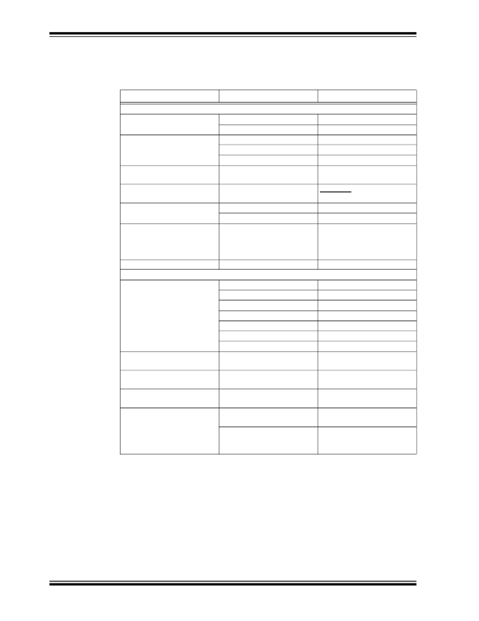
CONVENTIONS USED IN THIS GUIDE
This manual uses the following documentation conventions:
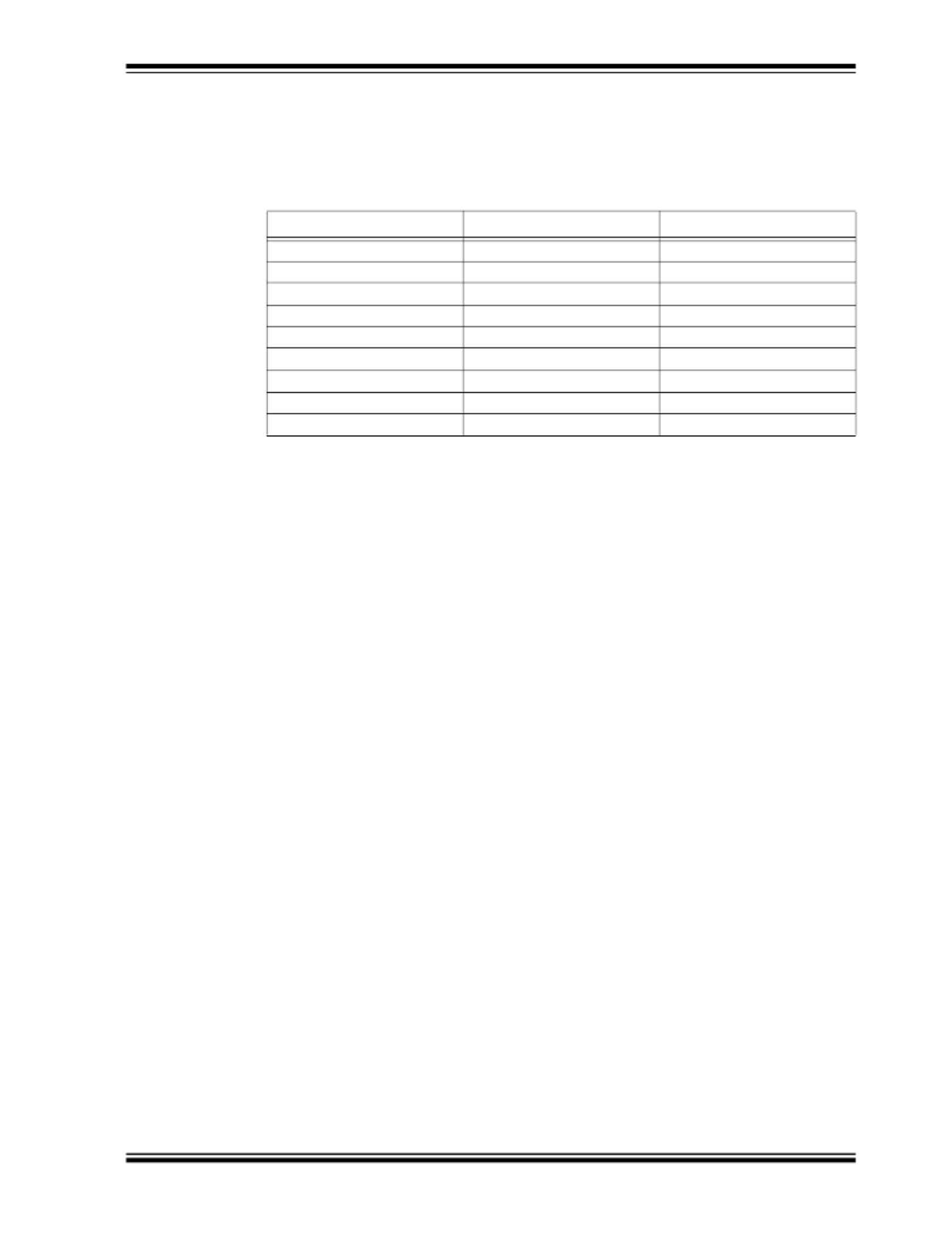
DOCUMENTATION CONVENTIONS
Description Represents Examples
Arial font:
Italic characters Referenced books MPLAB® IDE User’s Guide
Emphasized text ...is the only compiler...
Initial caps A window the Output window
A dialog the Settings dialog
A menu selection select Enable Programmer
Quotes A field name in a window or
dialog
“Save project before build”
Underlined, italic text with
right angle bracket
A menu path File>Save
Bold characters A dialog button Click OK
A tab Click the Power tab
N‘Rnnnn A number in verilog format,
where N is the total number of
digits, R is the radix and n is a
digit.
4‘b0010, 2‘hF1
Text in angle brackets < > A key on the keyboard Press <Enter>, <F1>
Courier New font:
Plain Courier New Sample source code #define START
Filenames autoexec.bat
File paths c:\mcc18\h
Keywords _asm, _endasm, static
Command-line options -Opa+, -Opa-
Bit values 0, 1
Constants 0xFF, ‘A’
Italic Courier New A variable argument file.o, where file can be
any valid filename
Square brackets [ ] Optional arguments mcc18 [options] file
[options]
Curly brackets and pipe
character: { | }
Choice of mutually exclusive
arguments; an OR selection
errorlevel {0|1}
Ellipses... Replaces repeated text var_name [,
var_name...]
Represents code supplied by
user
void main (void)
{ ...
}

XPRO User’s Guide
DS50003049A-page 6 2021 Microchip Technology Inc.
email: SJO-FTD.GBUTechSupport@microchip.com
Internet: www.microsemi.com/ftdsupport
Europe, Middle East, and Africa (EMEA)
Microchip FTS Services and Support EMEA
Altlaufstrasse 42
85635 Hoehenkirchen-Siegertsbrunn
Germany
Telephone: +49 700 3288 6435
Fax: +49 8102 8961 533
email: ftd.emeasupport@microsemi.com
email: ftd.emea_sales@microsemi.com
THE MICROCHIP WEBSITE
Microchip provides online support via our website at www.microchip.com. This website
is used as a means to make files and information easily available to customers.
Accessible by using your favorite Internet browser, the website contains the following
information:
•Product Support – Data sheets and errata, application notes and sample
programs, design resources, user’s guides and hardware support documents,
latest software releases and archived software
•General Technical Support – Frequently Asked Questions (FAQs), technical
support requests, online discussion groups, Microchip consultant program
member listing
•Business of Microchip – Product selector and ordering guides, latest Microchip
press releases, listing of seminars and events, listings of Microchip sales offices,
distributors and factory representatives
CUSTOMER SUPPORT
Users of Microchip products can receive assistance through several channels:
• Distributor or Representative
• Local Sales Office
• Field Application Engineer (FAE)
• Technical Support
Customers should contact their distributor, representative or field application engineer
(FAE) for support. Local sales offices are also available to help customers. A listing of
sales offices and locations is included in the back of this document.
Technical support is available through the website at:
http://www.microchip.com/support.
DOCUMENT REVISION HISTORY
Revision A (February 2021)
• Initial release of this document as Microchip DS50003049A.

XPRO USER’S GUIDE
2021 Microchip Technology Inc. DS50003049A-page 7
Table of Contents
Preface ........................................................................................................................... 3
Purpose of This Guide........................................................................................... 3
Who Should Read This Guide............................................................................... 3
Document Layout .................................................................................................. 3
Conventions Used in this Guide ............................................................................ 4
Warnings, Cautions, Recommendations, and Notes............................................. 5
Where to Find Answers to Product and Document Questions .............................. 5
Related Documents and Information..................................................................... 5
The Microchip Website.......................................................................................... 6
Customer Support ................................................................................................. 6
Document Revision History ................................................................................... 6
Chapter 1. Product Overview
1.1 Typical Applications......................................................................................... 9
1.2 Specifications ................................................................................................ 10
1.2.1 XPRO Electrical Specifications................................................................... 10
1.2.2 XPRO Connectors...................................................................................... 11
1.2.3 XPRO MTBF: Ground Benign (GB) Prediction........................................... 12
Chapter 2. Operation and Installation
2.1 Theory of Operation ...................................................................................... 13
2.2 Installation ..................................................................................................... 14
2.2.1 Site Selection ............................................................................................. 14
2.2.2 Cabling ....................................................................................................... 14
2.2.3 Turn-On Procedure .................................................................................... 14
2.2.4 Frequency Adjustment Procedure .............................................................. 15
2.2.5 Synchronizing to an External 1PPS Signal ................................................ 16
2.2.6 Maintenance and Repairs .......................................................................... 16
Chapter 3. Design Integration Considerations
3.1 XPRO Mechanical Drawings ......................................................................... 17
3.2 Thermal Considerations ................................................................................ 17
3.2.1 Thermal Tape Use...................................................................................... 17
3.2.2 Heat Sink .................................................................................................... 17
3.2.3 Impact of External Ambient Air Temperature on Unit Operation ................ 17
3.2.4 Unit Operating Temperature Range ........................................................... 18
3.2.5 Frequency Offset from Water Condensation.............................................. 19
3.3 External Interfacing and Grounding............................................................... 19
3.3.1 XPRO Serial Port Protocol ......................................................................... 20
3.3.2 Lock (BITE) Signal ..................................................................................... 21
3.3.3 Service Signal ............................................................................................ 21
3.3.4 Frequency Control ...................................................................................... 21

XPRO User’s Guide
DS50003049A-page 8 2021 Microchip Technology Inc.
3.4 Temperature Compensation of Frequency.................................................... 21
3.5 EMI Considerations....................................................................................... 22
3.5.1 Outer Mu-Metal Cover ................................................................................22
3.6 XPRO Susceptibility to Input Noise............................................................... 22
3.7 XPRO Maintenance....................................................................................... 23
3.7.1 XPRO Design Goal .....................................................................................23
Worldwide Sales and Service .....................................................................................25
XPRO USER’S GUIDE
2021 Microchip Technology Inc. DS50003049A-page 9
Chapter 1. Functional Descriptions
The XPRO is part of Microchip's family of precision frequency generator components.
It is designed to easily integrate into a system, requiring only one input supply voltage
and allowing direct plug-in connection into another circuit board. It offers the reliability
of a design that has been refined over many years from the experience gained in field-
ing tens of thousands of Microchip oscillators.
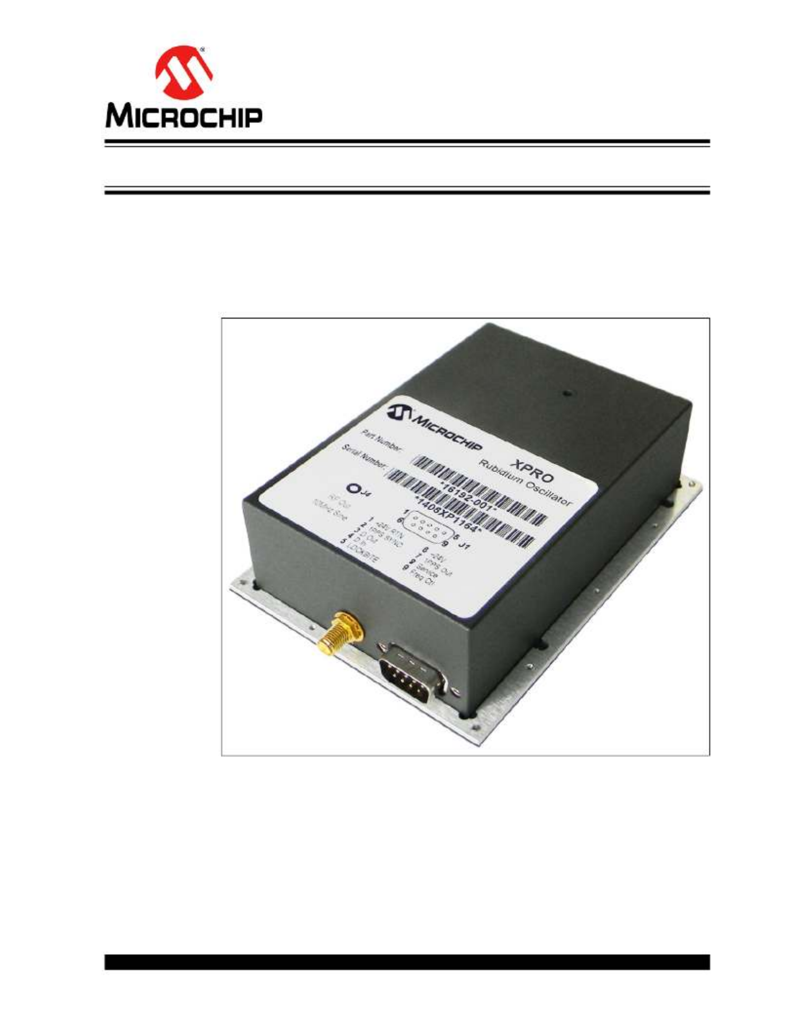
The following illustration shows the XPRO high-performance rubidium oscillator.
FIGURE 1-1: XPRO High-Performance Rubidium Oscillator.
1.1 TYPICAL APPLICATIONS
The XPRO is a product that Microchip offers for those who require a high-performance
rubidium atomic frequency standard in their system design. The XPRO is designed for
ease of integration into time and frequency systems because of its low-profile and sin-
gle-circuit board design. The height and footprint are designed to accommodate a 1U
VME application, or a 3U VME application. Great care has been taken in the design to
minimize EMI emissions and susceptibility, including the use of an outer mu-metal
cover. The XPRO complies with the FCC Article 47, Code of Federal Rules, Part 15,
Class B. The operation is subject to the following two conditions.

XPRO User’s Guide
DS50003049A-page 10 2021 Microchip Technology Inc.
• This device may not cause harmful interference.
• This device must accept any interference received, including interference that
may cause undesired operation.
The XPRO also complies with EN55022B and EN50082-1. For more information, see
the XPRO data sheet.
The technology utilized in the design of the XPRO has been successfully applied to
telecom networks, such as digital cellular/PCS base stations, SONET/SDH digital net-
work timing, and aerospace and defense applications (such as secure communications
systems and satellite ground-stations). Linked with a GPS receiver, the XPRO provides
the necessary timing requirements for CDMA cellular and PCS systems. The low-tem-
perature coefficient and excellent frequency stability extend holdover performance
when the GPS signal is not available.
The XPRO is designed for long operating periods without maintenance (long-life Rb
lamp, extended crystal control range) with a goal to exceed 10 years. The design pro-
vides a stable frequency with go ability, and excellent spur od short- and long-term st
performance.
The XPRO provides a 5V CMOS-compatible alarm signal derived from the basic phys-
ics operation, which indicates when the output frequency is outside roughly ±5 × 10⁻⁸
of absolute frequency offset.
1.2 SPECIFICATIONS
The following sections provide details on the specifications for the XPRO device.
1.2.1 XPRO Electrical Specifications
The following are outputs for the XPRO electrical specifications.
• 10 MHz Sine Wave
- Level: 7.8 dBm ±0.8 dBm (0.55VRMS ±0.05VRMS)
- Impedance load: 50Ω
• 1PPS
- Polarity: Positive
- Pulse width: 20 μs
- Rise/fall time: ≤5 ns (with a 15 pF load)
- Logic level: VL < 0.55V, VH > 4.2V (with a 15 pF load)
- RMS jitter: ≤1 ns
- JamSync accuracy: 10 ns
• Lock status (BITE) 5V CMOS
- Lock: 0V to <0.55V
- Unlock: 4.2V to 5V
• Service status 5V CMOS
- Low: 0V to <0.55V
- High: 4.2V to 5V
The following are inputs for the XPRO electrical specifications.
• 1PPS Sync
- VIL: 0V to 0.8V
- VIH: 2.2V to 3.8V
Note: This information is subject to change. Consult the XPRO data sheet for the
most up-to-date list of specifications.
Functional Descriptions
2021 Microchip Technology Inc. DS50003049A-page 11
• Analog range (±1.5 × 10⁻⁹)
- 0VDC to 5VDC
• Input voltage range
- 19VDC to 32VDC
RS-232 control/monitor interface
- Baud rate: 57,600
- Data bits: 8
- Parity: None
- Stop bits: 1
- Flow control: None
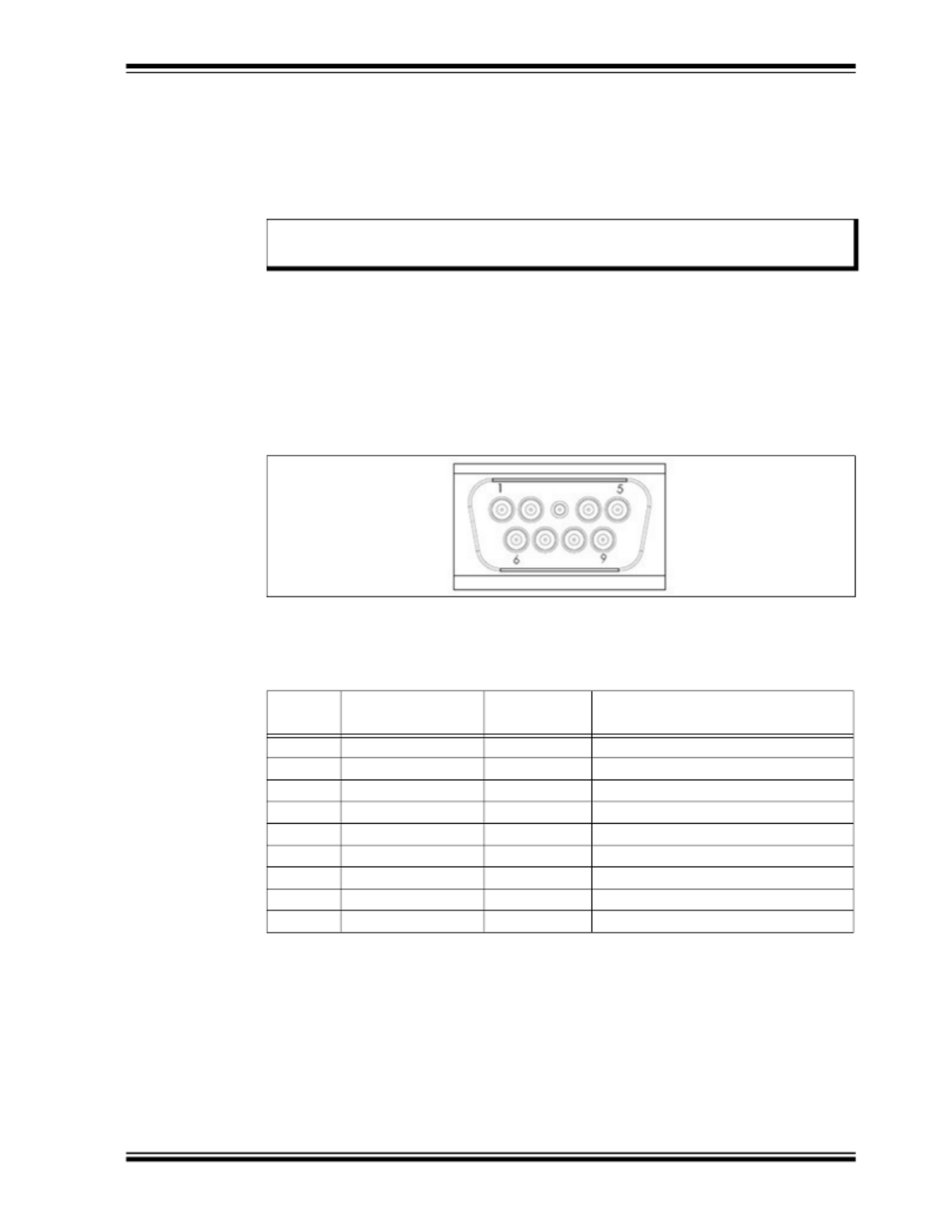
1.2.2 XPRO Connectors
The following illustration shows the J1 connector.
FIGURE 1-2: J1 Connector.
The following table lists the J1 signals.
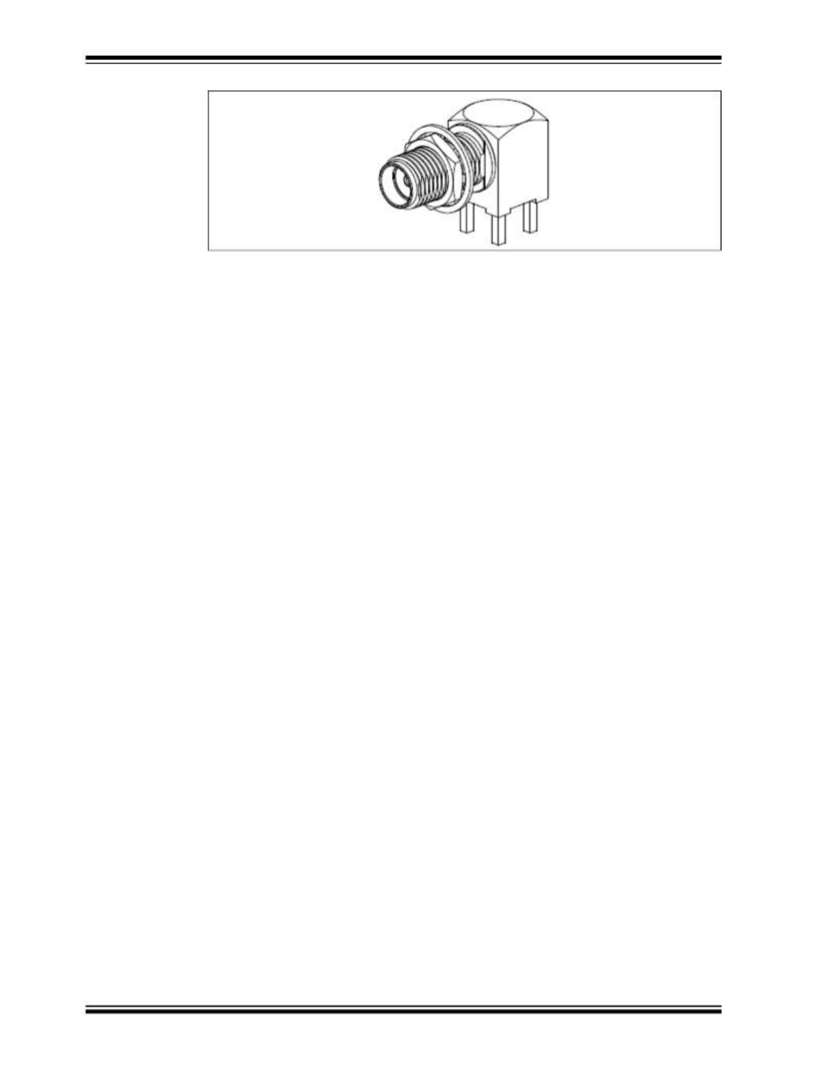
The following illustration shows the J4 connector for the 10 MHz sine output (SMA
FEMALE, MIL-PRF-39012).
Note: Voltage levels are 3.3V CMOS. A “level-shift” device should be employed
to achieve true RS-232 levels.
TABLE 1-1: J1 SIGNALS
Pin
Number Signal Name Type Signal Function
1 24V RTN GND Power return to chassis ground
2 1PPS IN — Sync to external 1PPS input
3 SERIAL DATA OUT 3.3V CMOS Digital steer and control
4 SERIAL DATA IN 3.3V CMOS Digital steer and control
5 LOCKBITE 5V CMOS Indication of lock status
6 24VDC PWR Power input
7 1PPS OUT 5V CMOS 1PPS output
8 SERVICE 5V CMOS Indication of service status
9 FREQCTL DC Analog steer
XPRO User’s Guide
DS50003049A-page 12 2021 Microchip Technology Inc.
FIGURE 1-3: J4 Connector.
Functional Descriptions
2021 Microchip Technology Inc. DS50003049A-page 13
1.2.3 XPRO MTBF: Ground Benign (GB) Prediction
The following table lists the predicted mean time between failure (MTBF) for the XPRO
in a ground benign (GB) environment.
TABLE 1-2: XPRO PREDICTED MTBF, GB
Temperature XPRO MTBF XPRO MTBF
20°C 950,976 hours 109 years
25°C 808,510 hours 92 years
30°C 679,036 hours 78 years
35°C 536,669 hours 64 years
40°C 462,792 hours 53 years
45°C 376,112 hours 43 years
50°C 302,799 hours 35 years
55°C 241,655 hours 28 years
60°C 191,277 hours 22 years
XPRO USER’S GUIDE
2021 Microchip Technology Inc. DS50003049A-page 15
Chapter 2. Operation and Installation
The following sections describe the operation and installation of the XPRO device.
2.1 THEORY OF OPERATION
The XPRO makes use of the atomic-resonance property of rubidium (87Rb) to control
the frequency of an unheated voltage-controlled crystal oscillator (VCXO) through a
frequency-locked loop (FLL).
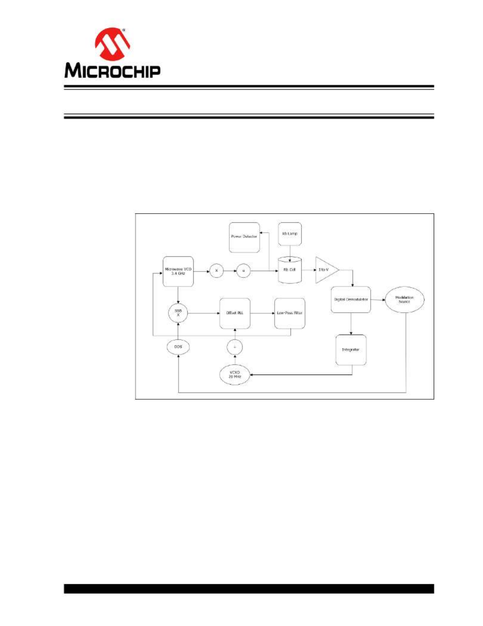
The following illustration shows a simplified function block diagram for the FLL.
FIGURE 2-1: XPRO Simplified Function Block Diagram.
A microwave signal is derived from a 20 MHz VCXO and applied to the 87Rb vapor
within a glass container or cell. The light of a rubidium spectral lamp also passes
through this cell and illuminates a photo detector. When the frequency of the applied
RF signal corresponds to the frequency of the ground-state hyperfine transition of the
87Rb atom (an ultra-stable high-Q rubidium atomic resonator), light is absorbed caus-
ing a change (decrease) in photo detector current (IPH).
As the change in current is small, modulation techniques are required to extract the
desired signal out of the noise background.
The dip in photo detector current is used to generate a control signal with phase and
amplitude information, which permits continuous atomic regulation of the VCXO fre-
quency. The servo section converts the photo detector current into a voltage, then
amplifies, digitizes, demodulates, and integrates it for high DC-servo loop gain.
The VCXO output signal is divided by two and is buffered to provide the standard fre-
quency output at 10 MHz. This signal is also frequency multiplied to microwave at
6.8346875 GHz through an offset locked phase lock loop (PLL) to interrogate the rubid-
XPRO User’s Guide
DS50003049A-page 16 2021 Microchip Technology Inc.
ium reference. The offset frequency is generated by a high-resolution direct digital syn-
thesizer (DDS) for tuning ability and the microwave power level is servo controlled to
minimize frequency instability caused by microwave power fluctuations.
2.2 INSTALLATION
The following sections provide details on installation for the XPRO device.
2.2.1 Site Selection
The XPRO installation site should be selected to maintain supply voltage and baseplate
temperatures in the product specifications range.
Make sure there are no strong magnetic fields at the site because XPRO is sensitive
to external DC- and AC-magnetic fields (see Section 1.2 “Specifications”). An exter-
nal magnetic field under 2 gauss should not result in measurable permanent frequency
offsets for XPRO.
2.2.2 Cabling
If desired, the XPRO is designed to directly mate to a user's interface board, saving the
cost and associated issues of interconnect cabling.
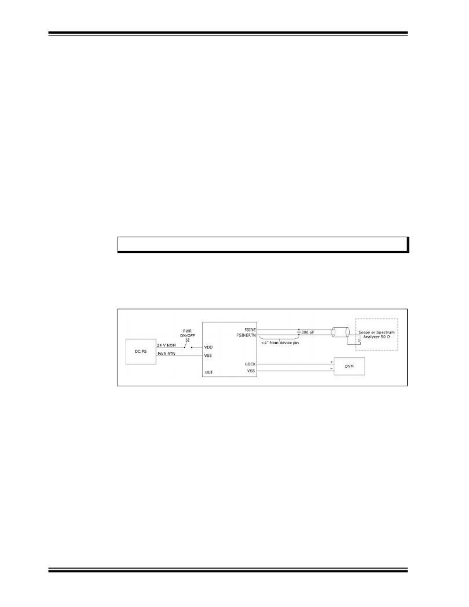
2.2.3 Turn-On Procedure
The XPRO does not have an on/off switch. The unit is powered up by plugging in the
unit's J1 connector to a properly terminated cable or the user's interface board. The fol-
lowing illustration shows a block diagram of a suggested hookup.
FIGURE 2-2: Block Diagram of Suggested XPRO Hookup.
The mating connector must provide power to J1-6 and power return to J1-1. The sys-
tem power supply must be capable of providing a peak source current of >1.5A during
the warm-up period. After warm-up, this power requirement drops to ~0.5A (room tem-
perature).
If the power supply is unable to provide the required peak amperage, then the XPRO
warm-up times will be degraded. If insufficient power is provided, the unit may be
unable to complete warm-up and a latch-up condition will result. This does not over
stress the electronics of the unit. However, it prevents the unit from achieving lock. It
can also cause rubidium migration in the lamp, which could prevent the unit from oper-
ating properly (it would require servicing).
The following are steps for turning on the XPRO:
1. Connect the RF load to the SMA female connector, J4.
2. Monitor the BITE signal at J1-5 with respect to chassis ground at J1-1, using a
high-impedance meter (recommended >1 MΩ input resistance).
3. Once the XPRO is plugged in and receiving power, wait 3 to 6 minutes while the
unit achieves atomic lock. During this period, the monitored BITE signal should
Note: Always use shielded cable and connectors to minimize EMI emissions.

XPRO User’s Guide
DS50003049A-page 18 2021 Microchip Technology Inc.
2.2.5 Synchronizing to an External 1PPS Signal
The following steps show how to synchronize to an external 1PPS signal.
1. Wait for clock to lock (see Lock (BITE) Signal (see page 13)).
2. Connect external 1PPS in (see XPRO Connectors (see page 5)).
3. Send command J (see XPRO Serial Port Protocol (see page 12)).
2.2.6 Maintenance and Repairs
The XPRO is not field repairable. If the unit should fail, do not remove the cover of the
unit and attempt to make repairs. Instead, call Microchip for the return procedure from
the Customer Support Group before returning the unit to Microchip.
XPRO USER’S GUIDE
2021 Microchip Technology Inc. DS50003049A-page 19
Chapter 3. Design Integration Considerations
The following sections provide details on the design integration considerations for the
XPRO device.
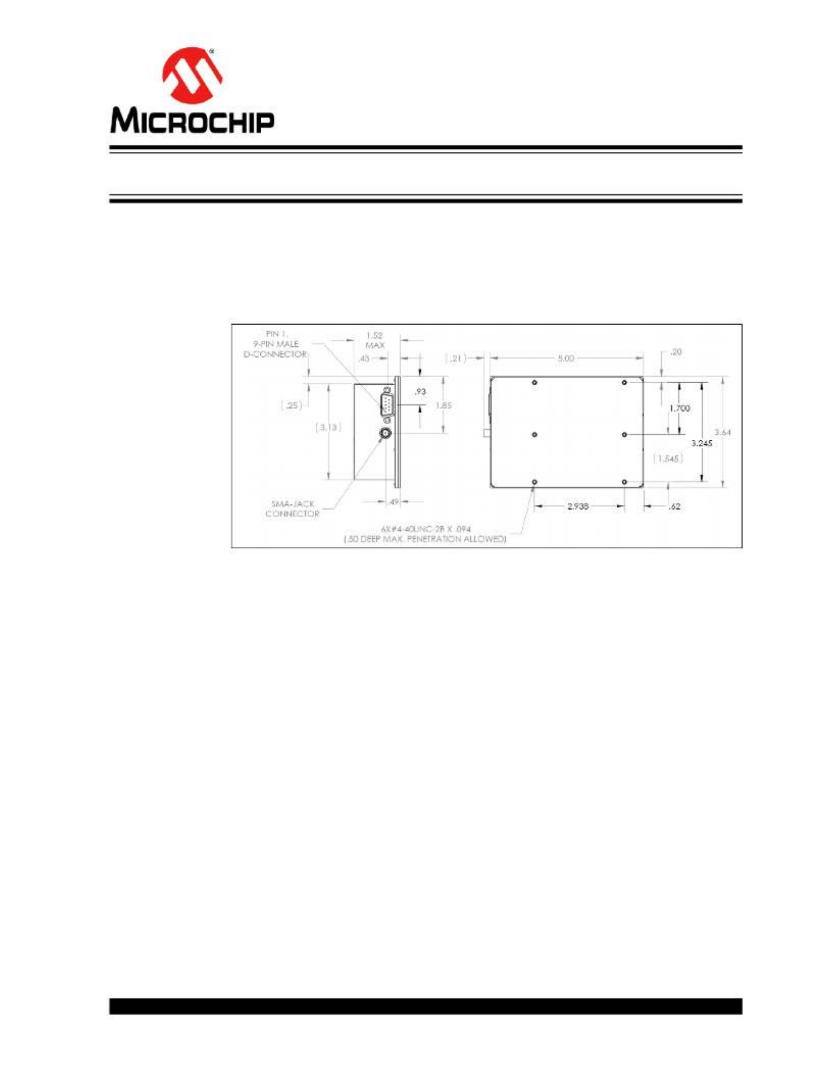
3.1 XPRO MECHANICAL DRAWINGS
The following illustration shows the XPRO mechanical drawing.
FIGURE 3-1: XPRO Mechanical Drawing.
3.2 THERMAL CONSIDERATIONS
The following sections describe the thermal considerations for the XPRO device.
3.2.1 Thermal Tape Use
It is critical to obtain a good thermal contact from the bottom (baseplate) of the XPRO
to the mounting surface in order to achieve the highest ambient operating temperature
for the specified XPRO operating baseplate temperature. It is also very important to
maintain a uniform heat sink temperature because of uneven heat flow into the base-
plate of the XPRO through its various mounting points.
3.2.2 Heat Sink
A heat sink or mounting baseplate is required to keep the baseplate temperature under
70°C. Internal self heating of the XPRO will cause local internal temperatures to exceed
Microchip’s part de-rating guidelines when used without a heat sink or forced air
(although the maximum manufacturer’s operating temperature ratings will not be
exceeded). A heat sink with thermal resistance to ambient of less than 2°C/W is
required for ambient of 50°C maximum.
3.2.3 Impact of External Ambient Air Temperature on Unit Operation
The power consumption for XPRO versus baseplate temperature is dominated by the
following mechanisms.
• The resonator heater power

XPRO User’s Guide
DS50003049A-page 20 2021 Microchip Technology Inc.
• The lamp heater power
• The electronics power
The resonator heater power is determined primarily by the resonator control tempera-
ture of 82°C, the baseplate temperature, and the 15.3°C/W thermal resistance from the
resonator to baseplate. The lamp heater power is determined primarily by the lamp
control temperature of 114°C, the baseplate temperature, and the 53°C/W thermal
resistance from the lamp to baseplate. Due to the unit’s internal 17V regulator, the elec-
tronics power reflects a fixed electronic current that is independent of input voltage. It
is roughly independent of baseplate temperature. The heater powers are roughly inde-
pendent of input voltage.
The XPRO maximum baseplate temperature described in the specifications was based
on a model where the unit was covered on 5 sides with 1-inch foam to simulate free
convection in air as the heat sink/baseplate was exposed to forced air.
The maximum operating baseplate temperature will be lower by several degrees Cel-
sius if the external air is hotter than the baseplate mounting. For example, a situation
where the baseplate is being cooled by a thermoelectric cooler, but the unit is exposed
to nearby heat-producing equipment.
If there is air flow over the unit’s top cover, the XPRO’s maximum operating baseplate
temperature will increase by 1°C or 2°C and its power consumption at a given base-
plate temperature will also increase by a few tens of milliwatts.
3.2.4 Unit Operating Temperature Range
There are three scenarios of interest concerning the operating temperature range for
XPRO (operating range –25°C to +70°C baseplate).
These three scenarios are differentiated by performance for the following conditions:
• The turn-on/warm-up period
• Standard operation after warm up is completed
• Emergency operation after warm up is completed
The turn-on/warm-up period includes the time for the internal heater circuits to obtain
thermal equilibrium, for the lamp to ignite into a plasma discharge, for the standard to
achieve atomic lock, and for the crystal operating temperature to reach its normal oper-
ating temperature range.
The following are the three scenarios:
• Scenario 1: The operating temperature range below the normal temperature
range without guaranteed warm up, but with full frequency control. Not recom-
mended and performance/specifications are not guaranteed.
• Scenario 2: The normal temperature range with full performance, including warm
up.
• Scenario 3: The operating temperature range above the normal temperature
range, excluding guaranteed warm up, but without loss of lock. Not recommended
and performance/specifications are not guaranteed.
The following describe all scenarios defined in terms of the unit’s baseplate tempera-
ture (the bottom surface of the bottom cover):
• Scenario 1 (not recommended) Temperature Range: –35°C to –25°C baseplate.
This operating temperature range allows full-frequency control, but excludes nor-
mal warm up. The cold-temperature limit is based on the use of a –30°C/+85°C
unheated crystal, and an internal temperature rise at the crystal of ~6°C.
• Scenario 2 Temperature Range: –25°C to +70°C baseplate. The normal operating
temperature range with specified warm-up capability included. This temperature
range excludes that of scenario 1, because of the unheated crystal used in the
Tuotetiedot
| Merkki: | Microchip |
| Kategoria: | Ei luokiteltu |
| Malli: | XPRO-Base-Perf-AT |
Tarvitsetko apua?
Jos tarvitset apua merkille Microchip XPRO-Base-Perf-AT esitä kysymys alla ja muut käyttäjät vastaavat sinulle
Ei luokiteltu Microchip Käyttöohjeet

12 Maaliskuuta 2025
12 Maaliskuuta 2025
25 Helmikuuta 2025
25 Helmikuuta 2025
25 Helmikuuta 2025
25 Helmikuuta 2025
25 Helmikuuta 2025
25 Helmikuuta 2025
25 Helmikuuta 2025
25 Helmikuuta 2025
Ei luokiteltu Käyttöohjeet
- Ei luokiteltu MSW
- Ei luokiteltu Stamos
- Ei luokiteltu Teka
- Ei luokiteltu Ulsonix
- Ei luokiteltu Aiwa
- Ei luokiteltu Maytag
- Ei luokiteltu Stamony
- Ei luokiteltu Laica
- Ei luokiteltu Thomson
- Ei luokiteltu Amana
- Ei luokiteltu Uniprodo
- Ei luokiteltu Miele
- Ei luokiteltu Whirlpool
- Ei luokiteltu ORNO
- Ei luokiteltu Ledlenser
- Ei luokiteltu Fujifilm
- Ei luokiteltu Etna
- Ei luokiteltu Haier
- Ei luokiteltu KitchenAid
- Ei luokiteltu Bauhn
- Ei luokiteltu Insignia
- Ei luokiteltu Royal Catering
- Ei luokiteltu LG
- Ei luokiteltu Bosch
- Ei luokiteltu Jocel
- Ei luokiteltu Power Dynamics
- Ei luokiteltu BEKO
- Ei luokiteltu Exquisit
- Ei luokiteltu Grundig
- Ei luokiteltu Hisense
- Ei luokiteltu Sharp
- Ei luokiteltu D-Link
- Ei luokiteltu Boneco
- Ei luokiteltu Electrolux
- Ei luokiteltu Apc
- Ei luokiteltu Severin
- Ei luokiteltu Café
- Ei luokiteltu Balay
- Ei luokiteltu DeWalt
- Ei luokiteltu Siemens
- Ei luokiteltu Hama
- Ei luokiteltu Petsafe
- Ei luokiteltu Vorago
- Ei luokiteltu Neewer
- Ei luokiteltu Jensen
- Ei luokiteltu Danby
- Ei luokiteltu Bartscher
- Ei luokiteltu Hartke
- Ei luokiteltu Gigabyte
- Ei luokiteltu Smeg
- Ei luokiteltu Gree
- Ei luokiteltu Hoover
- Ei luokiteltu EBERLE
- Ei luokiteltu Hazet
- Ei luokiteltu Fluke
- Ei luokiteltu Philips
- Ei luokiteltu Goobay
- Ei luokiteltu Topeak
- Ei luokiteltu Antari
- Ei luokiteltu Thermex
- Ei luokiteltu TCL
- Ei luokiteltu Russell Hobbs
- Ei luokiteltu Panduit
- Ei luokiteltu IFM
- Ei luokiteltu Avantree
- Ei luokiteltu Hotpoint
- Ei luokiteltu Schwaiger
- Ei luokiteltu Nabo
- Ei luokiteltu Arendo
- Ei luokiteltu Godox
- Ei luokiteltu Megger
- Ei luokiteltu Balam Rush
- Ei luokiteltu Noxon
- Ei luokiteltu Amica
- Ei luokiteltu Sanus
- Ei luokiteltu Adidas
- Ei luokiteltu Domo
- Ei luokiteltu IKEA
- Ei luokiteltu Cayin
- Ei luokiteltu AEG
- Ei luokiteltu Reflexion
- Ei luokiteltu TP Link
- Ei luokiteltu Inventum
- Ei luokiteltu Totolink
- Ei luokiteltu Shokz
- Ei luokiteltu Gamma
- Ei luokiteltu Artusi
- Ei luokiteltu Medel
- Ei luokiteltu Meris
- Ei luokiteltu Navitel
- Ei luokiteltu Meridian
- Ei luokiteltu Cecotec
- Ei luokiteltu AeroCool
- Ei luokiteltu Kugoo
- Ei luokiteltu Rikon
- Ei luokiteltu Samsung
- Ei luokiteltu Neff
- Ei luokiteltu Garmin
- Ei luokiteltu Razer
- Ei luokiteltu Teufel
- Ei luokiteltu Enermax
- Ei luokiteltu Noveen
- Ei luokiteltu Fender
- Ei luokiteltu StarTech.com
- Ei luokiteltu Origin Storage
- Ei luokiteltu Outwell
- Ei luokiteltu Best
- Ei luokiteltu Stihl
- Ei luokiteltu Delonghi
- Ei luokiteltu Kostal
- Ei luokiteltu ZOTAC
- Ei luokiteltu Comfee
- Ei luokiteltu Imarflex
- Ei luokiteltu Edgestar
- Ei luokiteltu Audient
- Ei luokiteltu Kogan
- Ei luokiteltu Solis
- Ei luokiteltu DJI
- Ei luokiteltu Snom
- Ei luokiteltu McIntosh
- Ei luokiteltu One For All
- Ei luokiteltu Caple
- Ei luokiteltu SereneLife
- Ei luokiteltu Turbosound
- Ei luokiteltu Behringer
- Ei luokiteltu Roesle
- Ei luokiteltu APSystems
- Ei luokiteltu Sony
- Ei luokiteltu GoGEN
- Ei luokiteltu Festo
- Ei luokiteltu Nitecore
- Ei luokiteltu Create
- Ei luokiteltu Furrion
- Ei luokiteltu Oreg
- Ei luokiteltu Glorious
- Ei luokiteltu Pro-Ject
- Ei luokiteltu Yamaha
- Ei luokiteltu CaviLock
- Ei luokiteltu OOONO
- Ei luokiteltu Xiaomi
- Ei luokiteltu Venom
- Ei luokiteltu Morel
- Ei luokiteltu Kichler
- Ei luokiteltu Topex
- Ei luokiteltu SMART Technologies
- Ei luokiteltu Trust
- Ei luokiteltu Neo
- Ei luokiteltu Morphy Richards
- Ei luokiteltu Newstar
- Ei luokiteltu Legrand
- Ei luokiteltu Integral LED
- Ei luokiteltu Goodram
- Ei luokiteltu Goldtouch
- Ei luokiteltu Lutec
- Ei luokiteltu Vello
- Ei luokiteltu Asus
- Ei luokiteltu Cudy
- Ei luokiteltu Midea
- Ei luokiteltu SBS
- Ei luokiteltu Hayter
- Ei luokiteltu BlueBuilt
- Ei luokiteltu Eufy
- Ei luokiteltu Gys
- Ei luokiteltu Conair
- Ei luokiteltu Turmix
- Ei luokiteltu Franke
- Ei luokiteltu Husqvarna
- Ei luokiteltu Sauber
- Ei luokiteltu Candy
- Ei luokiteltu Shimano
- Ei luokiteltu Axis
- Ei luokiteltu Tamron
- Ei luokiteltu Liebherr
- Ei luokiteltu Carson
- Ei luokiteltu Gourmetmaxx
- Ei luokiteltu Viking
- Ei luokiteltu Gembird
- Ei luokiteltu Truelife
- Ei luokiteltu AkYtec
- Ei luokiteltu Busch-Jaeger
- Ei luokiteltu ETA
- Ei luokiteltu Voltcraft
- Ei luokiteltu Axor
- Ei luokiteltu Duravit
- Ei luokiteltu Karran
- Ei luokiteltu Elkay
- Ei luokiteltu Brennenstuhl
- Ei luokiteltu Extron
- Ei luokiteltu My Wall
- Ei luokiteltu Lindy
- Ei luokiteltu HP
- Ei luokiteltu HiLook
- Ei luokiteltu Aputure
- Ei luokiteltu Netgear
- Ei luokiteltu BaByliss
- Ei luokiteltu Honor
- Ei luokiteltu XP-PEN
- Ei luokiteltu Danfoss
- Ei luokiteltu Riccar
- Ei luokiteltu Orbegozo
- Ei luokiteltu Media-tech
- Ei luokiteltu Kuppersbusch
- Ei luokiteltu BOYA
- Ei luokiteltu Mebby
- Ei luokiteltu Pioneer
- Ei luokiteltu NEO Tools
- Ei luokiteltu TONI&GUY
- Ei luokiteltu Gorenje
- Ei luokiteltu Summit
- Ei luokiteltu Accucold
- Ei luokiteltu EarFun
- Ei luokiteltu Toolcraft
- Ei luokiteltu Gram
- Ei luokiteltu WarmlyYours
- Ei luokiteltu Gemini
- Ei luokiteltu Somfy
- Ei luokiteltu Lorex
- Ei luokiteltu Catit
- Ei luokiteltu NuPrime
- Ei luokiteltu Ecler
- Ei luokiteltu Roccat
- Ei luokiteltu AudioControl
- Ei luokiteltu Elsner
- Ei luokiteltu Kask
- Ei luokiteltu Digitus
- Ei luokiteltu Stokke
- Ei luokiteltu Cabasse
- Ei luokiteltu Koenic
- Ei luokiteltu Panasonic
- Ei luokiteltu Beaphar
- Ei luokiteltu Sure Petcare
- Ei luokiteltu Rotel
- Ei luokiteltu Livall
- Ei luokiteltu KEF
- Ei luokiteltu Monogram
- Ei luokiteltu Sortimo
- Ei luokiteltu Unicol
- Ei luokiteltu Audio-Technica
- Ei luokiteltu Olimpia Splendid
- Ei luokiteltu Lian Li
- Ei luokiteltu JLab
- Ei luokiteltu Toa
- Ei luokiteltu Marantz
- Ei luokiteltu Knog
- Ei luokiteltu Rega
- Ei luokiteltu Vox
- Ei luokiteltu Mars Gaming
- Ei luokiteltu Kerbl
- Ei luokiteltu Metra
- Ei luokiteltu Pyle
- Ei luokiteltu Westinghouse
- Ei luokiteltu Sencor
- Ei luokiteltu Cello
- Ei luokiteltu Hobby
- Ei luokiteltu Lenovo
- Ei luokiteltu Medion
- Ei luokiteltu Noctua
- Ei luokiteltu Klein Tools
- Ei luokiteltu LevelOne
- Ei luokiteltu Shure
- Ei luokiteltu Michael Todd Beauty
- Ei luokiteltu GRAUGEAR
- Ei luokiteltu Trixie
- Ei luokiteltu Schneider
- Ei luokiteltu Lorelli
- Ei luokiteltu Roland
- Ei luokiteltu OBSBOT
- Ei luokiteltu Epson
- Ei luokiteltu SuperTooth
- Ei luokiteltu Kluge
- Ei luokiteltu Bobrick
- Ei luokiteltu Signature Hardware
- Ei luokiteltu Martin
- Ei luokiteltu Kanto
- Ei luokiteltu Scott
- Ei luokiteltu Delta
- Ei luokiteltu Kindermann
- Ei luokiteltu Robern
- Ei luokiteltu Hortus
- Ei luokiteltu DeLock
- Ei luokiteltu Bertazzoni
- Ei luokiteltu Coyote
- Ei luokiteltu Kidde
- Ei luokiteltu Anker
- Ei luokiteltu Growatt
- Ei luokiteltu Nanoleaf
- Ei luokiteltu Stirling
- Ei luokiteltu Mistral
- Ei luokiteltu JVC
- Ei luokiteltu VMV
- Ei luokiteltu S.M.S.L
- Ei luokiteltu Privileg
- Ei luokiteltu MPM
- Ei luokiteltu Niceboy
- Ei luokiteltu Engenius
- Ei luokiteltu Khind
- Ei luokiteltu Motorola
- Ei luokiteltu EMOS
- Ei luokiteltu CyberPower
- Ei luokiteltu Sharper Image
- Ei luokiteltu RGBlink
- Ei luokiteltu Clean Air Optima
- Ei luokiteltu Manfrotto
- Ei luokiteltu Cosatto
- Ei luokiteltu Lego
- Ei luokiteltu Fluval
- Ei luokiteltu Cleco
- Ei luokiteltu Kicker
- Ei luokiteltu Bauknecht
- Ei luokiteltu Gude
- Ei luokiteltu Auna
- Ei luokiteltu Taurus
- Ei luokiteltu Heatit
- Ei luokiteltu Midland
- Ei luokiteltu Field Optics
- Ei luokiteltu Zebra
- Ei luokiteltu Yealink
- Ei luokiteltu FIMI
- Ei luokiteltu Optex
- Ei luokiteltu Frigidaire
- Ei luokiteltu Levoit
- Ei luokiteltu Deye
- Ei luokiteltu Dimplex
- Ei luokiteltu OSD Audio
- Ei luokiteltu Nibe
- Ei luokiteltu Ryobi
- Ei luokiteltu Dremel
- Ei luokiteltu Breville
- Ei luokiteltu Kodak
- Ei luokiteltu Velleman
- Ei luokiteltu Sharkoon
- Ei luokiteltu Laserliner
- Ei luokiteltu Segway
- Ei luokiteltu Cameo
- Ei luokiteltu Casio
- Ei luokiteltu DataVideo
- Ei luokiteltu RGV
- Ei luokiteltu Hendi
- Ei luokiteltu Gamdias
- Ei luokiteltu Concept
- Ei luokiteltu BeamZ
- Ei luokiteltu Livoo
- Ei luokiteltu Nexa
- Ei luokiteltu Guzzanti
- Ei luokiteltu XO
- Ei luokiteltu Steinel
- Ei luokiteltu Bluesound
- Ei luokiteltu Flex
- Ei luokiteltu Chauvin Arnoux
- Ei luokiteltu Blackstar
- Ei luokiteltu Caso
- Ei luokiteltu Hertz
- Ei luokiteltu Kenwood
- Ei luokiteltu Cambridge
- Ei luokiteltu Nobo
- Ei luokiteltu Dell
- Ei luokiteltu Ciarra
- Ei luokiteltu Brandson
- Ei luokiteltu Mybeo
- Ei luokiteltu Aplic
- Ei luokiteltu CSL
- Ei luokiteltu Zoom
- Ei luokiteltu Tru Components
- Ei luokiteltu Hitachi
- Ei luokiteltu Fisher Paykel
- Ei luokiteltu Bearware
- Ei luokiteltu Moen
- Ei luokiteltu Fulgor Milano
- Ei luokiteltu Viewsonic
- Ei luokiteltu B-tech
- Ei luokiteltu Hyundai
- Ei luokiteltu IMM Photonics
- Ei luokiteltu Hansgrohe
- Ei luokiteltu Maginon
- Ei luokiteltu Speco Technologies
- Ei luokiteltu Nec
- Ei luokiteltu IFi Audio
- Ei luokiteltu Tripp Lite
- Ei luokiteltu Nevir
- Ei luokiteltu Infiniton
- Ei luokiteltu Sennheiser
- Ei luokiteltu Ag Neovo
- Ei luokiteltu Henry Engineering
- Ei luokiteltu Taco Tuesday
- Ei luokiteltu Wire Technologies
- Ei luokiteltu GPO
- Ei luokiteltu Block
- Ei luokiteltu Maxi-Cosi
- Ei luokiteltu Ufesa
- Ei luokiteltu Milwaukee
- Ei luokiteltu Smart-AVI
- Ei luokiteltu CEEM
- Ei luokiteltu CAME-TV
- Ei luokiteltu A-Designs
- Ei luokiteltu EchoMaster
- Ei luokiteltu Krups
- Ei luokiteltu Crimson
- Ei luokiteltu Elgato
- Ei luokiteltu Corsair
- Ei luokiteltu Generac
- Ei luokiteltu EVE
- Ei luokiteltu Dahua Technology
- Ei luokiteltu Cambium Networks
- Ei luokiteltu Safety 1st
- Ei luokiteltu Scarlett
- Ei luokiteltu Axxess
- Ei luokiteltu Advance
- Ei luokiteltu Indesit
- Ei luokiteltu Daikin
- Ei luokiteltu Shoprider
- Ei luokiteltu Canon
- Ei luokiteltu Rowenta
- Ei luokiteltu VAIS Technology
- Ei luokiteltu Zephyr
- Ei luokiteltu Maxsa
- Ei luokiteltu Kern
- Ei luokiteltu Lincoln Electric
- Ei luokiteltu BRIO
- Ei luokiteltu Taylor
- Ei luokiteltu AXESS
- Ei luokiteltu DAB
- Ei luokiteltu Be Cool
- Ei luokiteltu Bluetti
- Ei luokiteltu Blaupunkt
- Ei luokiteltu Thermaltake
- Ei luokiteltu Artsound
- Ei luokiteltu Simrad
- Ei luokiteltu Volcano
- Ei luokiteltu Nordic Winter
- Ei luokiteltu TechBite
- Ei luokiteltu Master
- Ei luokiteltu NEP
- Ei luokiteltu Catlink
- Ei luokiteltu Cablexpert
- Ei luokiteltu Ansmann
- Ei luokiteltu Røde
- Ei luokiteltu Makita
- Ei luokiteltu Einhell
- Ei luokiteltu Avidsen
- Ei luokiteltu Elac
- Ei luokiteltu Lewitt
- Ei luokiteltu Anova
- Ei luokiteltu Posiflex
- Ei luokiteltu Planet
- Ei luokiteltu Biostar
- Ei luokiteltu Mitsubishi
- Ei luokiteltu HeadRush
- Ei luokiteltu Marshall
- Ei luokiteltu Showtec
- Ei luokiteltu PCE
- Ei luokiteltu Hikvision
- Ei luokiteltu Sitecom
- Ei luokiteltu Navman
- Ei luokiteltu JIMMY
- Ei luokiteltu Equip
- Ei luokiteltu Conceptronic
- Ei luokiteltu Sirius
- Ei luokiteltu Noyafa
- Ei luokiteltu Yorkville
- Ei luokiteltu Toro
- Ei luokiteltu Intermatic
- Ei luokiteltu Spear & Jackson
- Ei luokiteltu Tower
- Ei luokiteltu Hubble Connected
- Ei luokiteltu McGregor
- Ei luokiteltu Habitat
- Ei luokiteltu MSR
- Ei luokiteltu Entes
- Ei luokiteltu V-Tac
- Ei luokiteltu Salton
- Ei luokiteltu Novation
- Ei luokiteltu Chipolino
- Ei luokiteltu Alphatronics
- Ei luokiteltu Fezz
- Ei luokiteltu Eden
- Ei luokiteltu Fuxtec
- Ei luokiteltu Graef
- Ei luokiteltu Megasat
- Ei luokiteltu SolaX Power
- Ei luokiteltu Valcom
- Ei luokiteltu Mikrotik
- Ei luokiteltu Yale
- Ei luokiteltu Mosconi
- Ei luokiteltu Mophie
- Ei luokiteltu Kohler
- Ei luokiteltu Envertec
- Ei luokiteltu Celly
- Ei luokiteltu Metabo
- Ei luokiteltu Jabra
- Ei luokiteltu Alphacool
- Ei luokiteltu Belanger
- Ei luokiteltu Cuisinart
- Ei luokiteltu Doepke
- Ei luokiteltu Lupine
- Ei luokiteltu Anton/Bauer
- Ei luokiteltu Acer
- Ei luokiteltu Dometic
- Ei luokiteltu JBL
- Ei luokiteltu Rigol
- Ei luokiteltu Joy-it
- Ei luokiteltu Body Solid
- Ei luokiteltu Infinity
- Ei luokiteltu DeepCool
- Ei luokiteltu Kali Audio
- Ei luokiteltu Chief
- Ei luokiteltu Majority
- Ei luokiteltu Cybex
- Ei luokiteltu Iiyama
- Ei luokiteltu Nedis
- Ei luokiteltu Crock-Pot
- Ei luokiteltu Helix
- Ei luokiteltu Genesis
- Ei luokiteltu Dyson
- Ei luokiteltu SKS
- Ei luokiteltu Elation
- Ei luokiteltu Magmatic
- Ei luokiteltu Supermicro
- Ei luokiteltu Zendure
- Ei luokiteltu Logilink
- Ei luokiteltu Majestic
- Ei luokiteltu Basetech
- Ei luokiteltu Leviton
- Ei luokiteltu Soundstream
- Ei luokiteltu Klipsch
- Ei luokiteltu PAC
- Ei luokiteltu Xaoc
- Ei luokiteltu Eldom
- Ei luokiteltu Fisher And Paykel
- Ei luokiteltu Hohner
- Ei luokiteltu Britax
- Ei luokiteltu Elba
- Ei luokiteltu Steiner
- Ei luokiteltu Vonroc
- Ei luokiteltu Worx
- Ei luokiteltu Brentwood
- Ei luokiteltu Philco
- Ei luokiteltu Bellari
- Ei luokiteltu Gossen Metrawatt
- Ei luokiteltu Rolls
- Ei luokiteltu MSI
- Ei luokiteltu Chauvet
- Ei luokiteltu Ordo
- Ei luokiteltu Ground Zero
- Ei luokiteltu OnePlus
- Ei luokiteltu V7
- Ei luokiteltu Jenn-Air
- Ei luokiteltu CRUX
- Ei luokiteltu Karma
- Ei luokiteltu Ridem
- Ei luokiteltu Glemm
- Ei luokiteltu StarIink
- Ei luokiteltu Prixton
- Ei luokiteltu HomeCraft
- Ei luokiteltu Nostalgia
- Ei luokiteltu GameDay
- Ei luokiteltu X-Lite
- Ei luokiteltu Söll
- Ei luokiteltu Sparkle
- Ei luokiteltu Edouard Rousseau
- Ei luokiteltu Lawn Star
- Ei luokiteltu Caberg
- Ei luokiteltu Exped
- Ei luokiteltu Igloo
- Ei luokiteltu Heusinkveld
- Ei luokiteltu KED
- Ei luokiteltu EPEVER
- Ei luokiteltu Grothe
- Ei luokiteltu Cane Creek
- Ei luokiteltu Swiss Eye
- Ei luokiteltu SilverStone
- Ei luokiteltu Goodis
- Ei luokiteltu Seiko
- Ei luokiteltu TFA
- Ei luokiteltu X Rocker
- Ei luokiteltu Dreame
- Ei luokiteltu Foreo
- Ei luokiteltu Speed-Link
- Ei luokiteltu Tesla
- Ei luokiteltu Aquael
- Ei luokiteltu Renkforce
- Ei luokiteltu Graff
- Ei luokiteltu Klarstein
- Ei luokiteltu Lauten Audio
- Ei luokiteltu Toddy
- Ei luokiteltu Lexivon
- Ei luokiteltu Icy Dock
- Ei luokiteltu Elta
- Ei luokiteltu ASI
- Ei luokiteltu Gurari
- Ei luokiteltu Varia
- Ei luokiteltu SPL
- Ei luokiteltu I-Tec
- Ei luokiteltu Xigmatek
- Ei luokiteltu Storcube
- Ei luokiteltu Tracer
- Ei luokiteltu Shark
- Ei luokiteltu REMKO
- Ei luokiteltu Phanteks
- Ei luokiteltu EnOcean
- Ei luokiteltu EK Water Blocks
- Ei luokiteltu Hoymiles
- Ei luokiteltu Envertech
- Ei luokiteltu Cougar
- Ei luokiteltu Asrock
- Ei luokiteltu Bestron
- Ei luokiteltu Audiotec Fischer
- Ei luokiteltu HMS Premium
- Ei luokiteltu PCE Instruments
- Ei luokiteltu Dedra
- Ei luokiteltu Furman
- Ei luokiteltu Abac
- Ei luokiteltu Cata
- Ei luokiteltu Vivax
- Ei luokiteltu Black Diamond
- Ei luokiteltu Advantech
- Ei luokiteltu Stanley
- Ei luokiteltu QSC
- Ei luokiteltu Bitspower
- Ei luokiteltu Black And Decker
- Ei luokiteltu Weston
- Ei luokiteltu Sauter
- Ei luokiteltu WHD
- Ei luokiteltu Schuberth
- Ei luokiteltu Q Acoustics
- Ei luokiteltu Scotsman
- Ei luokiteltu Plantronics
- Ei luokiteltu Proctor Silex
- Ei luokiteltu Radial Engineering
- Ei luokiteltu Karcher
- Ei luokiteltu Orion
- Ei luokiteltu A-NeuVideo
- Ei luokiteltu Beem
- Ei luokiteltu Atlona
- Ei luokiteltu EZ Dupe
- Ei luokiteltu Becken
- Ei luokiteltu I-PRO
- Ei luokiteltu DVDO
- Ei luokiteltu GoXtreme
- Ei luokiteltu Primacoustic
- Ei luokiteltu Avanti
- Ei luokiteltu Acros
- Ei luokiteltu Phil And Teds
- Ei luokiteltu Jotul
- Ei luokiteltu Thermarest
- Ei luokiteltu Powerplus
- Ei luokiteltu Ozito
- Ei luokiteltu Vivanco
- Ei luokiteltu TC Electronic
- Ei luokiteltu Suzuki
- Ei luokiteltu Bionaire
- Ei luokiteltu Huslog
- Ei luokiteltu Glem Gas
- Ei luokiteltu Apogee
- Ei luokiteltu Atomos
- Ei luokiteltu IOptron
- Ei luokiteltu Palmer
- Ei luokiteltu R-Go Tools
- Ei luokiteltu Drayton
- Ei luokiteltu Spektrum
- Ei luokiteltu Jung
- Ei luokiteltu Götze & Jensen
- Ei luokiteltu Native Instruments
- Ei luokiteltu Homedics
- Ei luokiteltu Xvive
- Ei luokiteltu True
- Ei luokiteltu AMX
- Ei luokiteltu Perlick
- Ei luokiteltu Uniden
- Ei luokiteltu Peavey
- Ei luokiteltu BenQ
- Ei luokiteltu Princess
- Ei luokiteltu FOX ESS
- Ei luokiteltu Waterstone
- Ei luokiteltu Mr Steam
- Ei luokiteltu Crown
- Ei luokiteltu DCS
- Ei luokiteltu Fresh N Rebel
- Ei luokiteltu DuroStar
- Ei luokiteltu Duromax
- Ei luokiteltu Owon
- Ei luokiteltu REVITIVE
- Ei luokiteltu Fosi Audio
- Ei luokiteltu Europalms
- Ei luokiteltu Nikon
- Ei luokiteltu HMD
- Ei luokiteltu Sven
- Ei luokiteltu Global Water
- Ei luokiteltu Hamilton Beach
- Ei luokiteltu Extech
- Ei luokiteltu Gaggia
- Ei luokiteltu Tunturi
- Ei luokiteltu Craftsman
- Ei luokiteltu SAVS
- Ei luokiteltu Hansa
- Ei luokiteltu Gastronoma
- Ei luokiteltu Lumens
- Ei luokiteltu Brizo
- Ei luokiteltu Xinfrared
- Ei luokiteltu Getac
- Ei luokiteltu ProLights
- Ei luokiteltu Phonak
- Ei luokiteltu Cherub
- Ei luokiteltu Luxul
- Ei luokiteltu Aruba
- Ei luokiteltu WiiM
- Ei luokiteltu Thor
- Ei luokiteltu Laurastar
- Ei luokiteltu Ambiano
- Ei luokiteltu Horizon
- Ei luokiteltu Bissell
- Ei luokiteltu Antelope Audio
- Ei luokiteltu ESYLUX
- Ei luokiteltu Austral
- Ei luokiteltu Y-brush
- Ei luokiteltu LiveU
- Ei luokiteltu RF-Links
- Ei luokiteltu Fortinge
- Ei luokiteltu Mercury
- Ei luokiteltu Vaddio
- Ei luokiteltu InFocus
- Ei luokiteltu Stinger
- Ei luokiteltu NEXTO DI
- Ei luokiteltu Abus
- Ei luokiteltu AV Tool
- Ei luokiteltu Adventure Kings
- Ei luokiteltu EQ Acoustics
- Ei luokiteltu Michigan
- Ei luokiteltu Vent-A-Hood
- Ei luokiteltu Audix
- Ei luokiteltu Vizio
- Ei luokiteltu Livarno Lux
- Ei luokiteltu Grillmeister
- Ei luokiteltu Ernesto
- Ei luokiteltu Neno
- Ei luokiteltu Rommelsbacher
- Ei luokiteltu One Control
- Ei luokiteltu Bome
- Ei luokiteltu Redback Technologies
- Ei luokiteltu ESX
- Ei luokiteltu City Theatrical
- Ei luokiteltu Omnitronic
- Ei luokiteltu Reber
- Ei luokiteltu Kaiser Nienhaus
- Ei luokiteltu Crestron
- Ei luokiteltu Eurolite
- Ei luokiteltu Manhattan
- Ei luokiteltu Miniland
- Ei luokiteltu Xavax
- Ei luokiteltu MOZA
- Ei luokiteltu Rocstor
- Ei luokiteltu Eureka
- Ei luokiteltu Cruz
- Ei luokiteltu Newland
- Ei luokiteltu Casalux
- Ei luokiteltu Edimax
- Ei luokiteltu Dragonshock
- Ei luokiteltu Russound
- Ei luokiteltu Adj
- Ei luokiteltu Olivetti
- Ei luokiteltu EVOLVEO
- Ei luokiteltu Stadler Form
- Ei luokiteltu Techno Line
- Ei luokiteltu MEE Audio
- Ei luokiteltu Wolfcraft
- Ei luokiteltu Monacor
- Ei luokiteltu Heinner
- Ei luokiteltu Minolta
- Ei luokiteltu Sena
- Ei luokiteltu Innoliving
- Ei luokiteltu Active Era
- Ei luokiteltu Aqara
- Ei luokiteltu POGS
- Ei luokiteltu Beghelli
- Ei luokiteltu BodyCraft
- Ei luokiteltu Superrollo
- Ei luokiteltu Mx Onda
- Ei luokiteltu Koolatron
- Ei luokiteltu Coca-Cola
- Ei luokiteltu Bixolon
- Ei luokiteltu Maruyama
- Ei luokiteltu Bravilor Bonamat
- Ei luokiteltu Kenmore
- Ei luokiteltu Hilti
- Ei luokiteltu D-Jix
- Ei luokiteltu Black Hydra
- Ei luokiteltu I.safe Mobile
- Ei luokiteltu Electro-Voice
- Ei luokiteltu Nimbus
- Ei luokiteltu Lowrance
- Ei luokiteltu Proscan
- Ei luokiteltu Roxio
- Ei luokiteltu Meireles
- Ei luokiteltu Accsoon
- Ei luokiteltu Inspire
- Ei luokiteltu Sebo
- Ei luokiteltu Wharfedale
- Ei luokiteltu Boss
- Ei luokiteltu Tannoy
- Ei luokiteltu Prompter People
- Ei luokiteltu Teltonika
- Ei luokiteltu JL Audio
- Ei luokiteltu Edesa
- Ei luokiteltu IOIO
- Ei luokiteltu Genexis
- Ei luokiteltu Buzz Rack
- Ei luokiteltu ZKTeco
- Ei luokiteltu Giordani
- Ei luokiteltu Cadel
- Ei luokiteltu Dualit
- Ei luokiteltu Atlas Sound
- Ei luokiteltu Solo
- Ei luokiteltu Realme
- Ei luokiteltu Wagner
- Ei luokiteltu Ariete
- Ei luokiteltu Bluestork
- Ei luokiteltu Davis
- Ei luokiteltu Comica
- Ei luokiteltu AddLiving
- Ei luokiteltu Melitta
- Ei luokiteltu Constructa
- Ei luokiteltu Lowell
- Ei luokiteltu INOGENI
- Ei luokiteltu Nearity
- Ei luokiteltu Kiloview
- Ei luokiteltu Middle Atlantic
- Ei luokiteltu Mount-It!
- Ei luokiteltu Morley
- Ei luokiteltu Ampeg
- Ei luokiteltu Apantac
- Ei luokiteltu Carry-on
- Ei luokiteltu Liftmaster
- Ei luokiteltu GVision
- Ei luokiteltu IPGARD
- Ei luokiteltu Murideo
- Ei luokiteltu TK Audio
- Ei luokiteltu Rosco
- Ei luokiteltu Proaim
- Ei luokiteltu Cisco
- Ei luokiteltu CGV
- Ei luokiteltu Vacmaster
- Ei luokiteltu Elmo
- Ei luokiteltu Libec
- Ei luokiteltu Point Source Audio
- Ei luokiteltu Macally
- Ei luokiteltu Linhof
- Ei luokiteltu Ade
- Ei luokiteltu MooreCo
- Ei luokiteltu Di4
- Ei luokiteltu Mellerware
- Ei luokiteltu Zenec
- Ei luokiteltu Silver Cross
- Ei luokiteltu Allen & Heath
- Ei luokiteltu American DJ
- Ei luokiteltu AJA
- Ei luokiteltu Postium
- Ei luokiteltu EXO
- Ei luokiteltu RME
- Ei luokiteltu SurgeX
- Ei luokiteltu Alcon
- Ei luokiteltu Vantec
- Ei luokiteltu Silverline
- Ei luokiteltu VAVA
- Ei luokiteltu Tefal
- Ei luokiteltu Vicoustic
- Ei luokiteltu LERAN
- Ei luokiteltu Doffler
- Ei luokiteltu Novy
- Ei luokiteltu Profoto
- Ei luokiteltu TensCare
- Ei luokiteltu Scanstrut
- Ei luokiteltu Mad Dog
- Ei luokiteltu Industrial Music Electronics
- Ei luokiteltu Source Audio
- Ei luokiteltu Black Lion Audio
- Ei luokiteltu Wiha
- Ei luokiteltu Puls Dimension
- Ei luokiteltu Wasp
- Ei luokiteltu OSEE
- Ei luokiteltu Gamewright
- Ei luokiteltu ISDT
- Ei luokiteltu Ilve
- Ei luokiteltu Scosche
- Ei luokiteltu Reolink
- Ei luokiteltu Bebob
- Ei luokiteltu Ashly
- Ei luokiteltu Claypaky
- Ei luokiteltu Premier Mounts
- Ei luokiteltu MuxLab
- Ei luokiteltu Icy Box
- Ei luokiteltu Holosun
- Ei luokiteltu Seagate
- Ei luokiteltu Holzmann
- Ei luokiteltu Blackmagic Design
- Ei luokiteltu Audiolab
- Ei luokiteltu Lectrosonics
- Ei luokiteltu Gravity
- Ei luokiteltu Modbap Modular
- Ei luokiteltu Ikan
- Ei luokiteltu Genius
- Ei luokiteltu Silvercrest
- Ei luokiteltu Rommer
- Ei luokiteltu Traeger
- Ei luokiteltu Memphis Audio
- Ei luokiteltu Focal
- Ei luokiteltu Belkin
- Ei luokiteltu BDI
- Ei luokiteltu Alpine
- Ei luokiteltu Ring
- Ei luokiteltu TC Helicon
- Ei luokiteltu TomTom
- Ei luokiteltu XGIMI
- Ei luokiteltu Omron
- Ei luokiteltu Celestron
- Ei luokiteltu Gymform
- Ei luokiteltu Glide Gear
- Ei luokiteltu Oppo
- Ei luokiteltu Chicco
- Ei luokiteltu AVM
- Ei luokiteltu Impact
- Ei luokiteltu Pelco
- Ei luokiteltu FoxFury
- Ei luokiteltu Argoclima
- Ei luokiteltu Mammut
- Ei luokiteltu Huawei
- Ei luokiteltu Escort
- Ei luokiteltu Heritage Audio
- Ei luokiteltu Safco
- Ei luokiteltu Monoprice
- Ei luokiteltu Stabila
- Ei luokiteltu CTA Digital
- Ei luokiteltu Olight
- Ei luokiteltu Primo
- Ei luokiteltu HammerSmith
- Ei luokiteltu Cyrus
- Ei luokiteltu Steelbody
- Ei luokiteltu Ltech
- Ei luokiteltu Ventev
- Ei luokiteltu Elektrobock
- Ei luokiteltu Triton
- Ei luokiteltu Trisa
- Ei luokiteltu Corberó
- Ei luokiteltu AENO
- Ei luokiteltu Korg
- Ei luokiteltu Atosa
- Ei luokiteltu STANDIVARIUS
- Ei luokiteltu Avteq
- Ei luokiteltu Techly
- Ei luokiteltu Izzy
- Ei luokiteltu PureLink
- Ei luokiteltu BirdDog
- Ei luokiteltu UNYKAch
- Ei luokiteltu TeachLogic
- Ei luokiteltu Al-ko
- Ei luokiteltu ADATA
- Ei luokiteltu Mobotix
- Ei luokiteltu Kramer
- Ei luokiteltu ATen
- Ei luokiteltu Blustream
- Ei luokiteltu Laserworld
- Ei luokiteltu Genelec
- Ei luokiteltu Kunft
- Ei luokiteltu Milesight
- Ei luokiteltu Honda
- Ei luokiteltu Spanninga
- Ei luokiteltu Perel
- Ei luokiteltu Bialetti
- Ei luokiteltu Xlyne
- Ei luokiteltu Plant Craft
- Ei luokiteltu Sungrow
- Ei luokiteltu Grundfos
- Ei luokiteltu Bazooka
- Ei luokiteltu Carlsbro
- Ei luokiteltu MoFi
- Ei luokiteltu Blackburn
- Ei luokiteltu Mtx Audio
- Ei luokiteltu Bang And Olufsen
- Ei luokiteltu Delta Dore
- Ei luokiteltu Sole Fitness
- Ei luokiteltu Cowon
- Ei luokiteltu Theben
- Ei luokiteltu Grasslin
- Ei luokiteltu Orbis
- Ei luokiteltu Fantini Cosmi
- Ei luokiteltu Bebe Confort
- Ei luokiteltu WHALE
- Ei luokiteltu Stalco
- Ei luokiteltu Bunn
- Ei luokiteltu Horizon Fitness
- Ei luokiteltu Cobra
- Ei luokiteltu Sonel
- Ei luokiteltu Lamax
- Ei luokiteltu Jilong
- Ei luokiteltu Maytronics
- Ei luokiteltu Tempmate
- Ei luokiteltu Idec
- Ei luokiteltu Analog Way
- Ei luokiteltu Gamesir
- Ei luokiteltu ZyXEL
- Ei luokiteltu Vogue
- Ei luokiteltu Frilec
- Ei luokiteltu Yaesu
- Ei luokiteltu Concept2
- Ei luokiteltu Musical Fidelity
- Ei luokiteltu Flir
- Ei luokiteltu Rademacher
- Ei luokiteltu NGS
- Ei luokiteltu CTOUCH
- Ei luokiteltu Girmi
- Ei luokiteltu Auray
- Ei luokiteltu RCF
- Ei luokiteltu KJB Security Products
- Ei luokiteltu Harvia
- Ei luokiteltu Homematic IP
- Ei luokiteltu Tektronix
- Ei luokiteltu WilTec
- Ei luokiteltu Easypix
- Ei luokiteltu LC-Power
- Ei luokiteltu SVS
- Ei luokiteltu 8BitDo
- Ei luokiteltu Pardini
- Ei luokiteltu Audeze
- Ei luokiteltu Be Quiet!
- Ei luokiteltu Ergobaby
- Ei luokiteltu Everdure
- Ei luokiteltu Tams Elektronik
- Ei luokiteltu Insta360
- Ei luokiteltu Fieldmann
- Ei luokiteltu Alpen Kreuzer
- Ei luokiteltu Xplora
- Ei luokiteltu H.Koenig
- Ei luokiteltu Wimberley
- Ei luokiteltu Playtive
- Ei luokiteltu Vimar
- Ei luokiteltu Osprey
- Ei luokiteltu Hosa
- Ei luokiteltu Havis
- Ei luokiteltu Pitsos
- Ei luokiteltu Lionelo
- Ei luokiteltu Physa
- Ei luokiteltu Steinberg
- Ei luokiteltu Daewoo
- Ei luokiteltu Emerson
- Ei luokiteltu Phoenix Gold
- Ei luokiteltu Aconatic
- Ei luokiteltu MBM
- Ei luokiteltu Oricom
- Ei luokiteltu Casablanca
- Ei luokiteltu Weasy
- Ei luokiteltu Biltema
- Ei luokiteltu Waves
- Ei luokiteltu Bogen
- Ei luokiteltu Electro Harmonix
- Ei luokiteltu Vocopro
- Ei luokiteltu Chrome-Q
- Ei luokiteltu Galaxy Audio
- Ei luokiteltu Altman
- Ei luokiteltu Aiphone
- Ei luokiteltu Atlas
- Ei luokiteltu Graco
- Ei luokiteltu Manta
- Ei luokiteltu MARTOR
- Ei luokiteltu Mean Well
- Ei luokiteltu Exelpet
- Ei luokiteltu Trendnet
- Ei luokiteltu G-Technology
- Ei luokiteltu CubuSynth
- Ei luokiteltu Simpson
- Ei luokiteltu Infasecure
- Ei luokiteltu SecureSafe
- Ei luokiteltu Intellinet
- Ei luokiteltu Hikoki
- Ei luokiteltu Emerio
- Ei luokiteltu Prime3
- Ei luokiteltu OBH Nordica
- Ei luokiteltu Butler
- Ei luokiteltu Duronic
- Ei luokiteltu AVer
- Ei luokiteltu IK Multimedia
- Ei luokiteltu Vankyo
- Ei luokiteltu Murr Elektronik
- Ei luokiteltu TDK-Lambda
- Ei luokiteltu Vitek
- Ei luokiteltu Quantum
- Ei luokiteltu Texas
- Ei luokiteltu Reloop
- Ei luokiteltu ProfiCook
- Ei luokiteltu Arovec
- Ei luokiteltu Harman Kardon
- Ei luokiteltu ARRI
- Ei luokiteltu Yamazen
- Ei luokiteltu Lantus
- Ei luokiteltu Acti
- Ei luokiteltu GMB Gaming
- Ei luokiteltu Eurom
- Ei luokiteltu Cadac
- Ei luokiteltu Olympia
- Ei luokiteltu Osram
- Ei luokiteltu Patching Panda
- Ei luokiteltu Consul
- Ei luokiteltu Draytek
- Ei luokiteltu Manitowoc
- Ei luokiteltu Joranalogue
- Ei luokiteltu Klavis
- Ei luokiteltu HyperX
- Ei luokiteltu KDK
- Ei luokiteltu ChamSys
- Ei luokiteltu Creative
- Ei luokiteltu OneTouch
- Ei luokiteltu Kospel
- Ei luokiteltu Crosscall
- Ei luokiteltu Dynacord
- Ei luokiteltu Rapoo
- Ei luokiteltu Suunto
- Ei luokiteltu Roidmi
- Ei luokiteltu IOGEAR
- Ei luokiteltu Ferguson
- Ei luokiteltu Adventuridge
- Ei luokiteltu Artecta
- Ei luokiteltu WyreStorm
- Ei luokiteltu IBEAM
- Ei luokiteltu ToughTested
- Ei luokiteltu Mattel
- Ei luokiteltu Baby Jogger
- Ei luokiteltu Savio
- Ei luokiteltu Healthy Choice
- Ei luokiteltu Yato
- Ei luokiteltu Lund
- Ei luokiteltu Oromed
- Ei luokiteltu Acefast
- Ei luokiteltu Porter-Cable
- Ei luokiteltu Christmas Time
- Ei luokiteltu Barazza
- Ei luokiteltu Chacon
- Ei luokiteltu Marmitek
- Ei luokiteltu Nivona
- Ei luokiteltu Thermador
- Ei luokiteltu Dehner
- Ei luokiteltu Eliminator Lighting
- Ei luokiteltu Microboards
- Ei luokiteltu Kopul
- Ei luokiteltu JoeCo
- Ei luokiteltu BZBGear
- Ei luokiteltu Fiilex
- Ei luokiteltu Gen Energy
- Ei luokiteltu DEERSYNC
- Ei luokiteltu ChyTV
- Ei luokiteltu Bresser
- Ei luokiteltu Arkon
- Ei luokiteltu Apollo Design
- Ei luokiteltu Ardes
- Ei luokiteltu Tesseract Modular
- Ei luokiteltu Zanussi
- Ei luokiteltu Bulgin
- Ei luokiteltu Foscam
- Ei luokiteltu AV:link
- Ei luokiteltu Pure 100
- Ei luokiteltu Hirschmann
- Ei luokiteltu Clatronic
- Ei luokiteltu Interphone
- Ei luokiteltu Kernau
- Ei luokiteltu Babybjörn
- Ei luokiteltu Hanseatic
- Ei luokiteltu Proline
- Ei luokiteltu Xblitz
- Ei luokiteltu Hager
- Ei luokiteltu Hecht
- Ei luokiteltu Konica Minolta
- Ei luokiteltu Neumann
- Ei luokiteltu Kathrein
- Ei luokiteltu STANDARD
- Ei luokiteltu BigBlue
- Ei luokiteltu RC Allen
- Ei luokiteltu Plastkon
- Ei luokiteltu Neutrik
- Ei luokiteltu Aquasure
- Ei luokiteltu Beautiful
- Ei luokiteltu Triplett
- Ei luokiteltu Alfatron
- Ei luokiteltu Bowflex
- Ei luokiteltu Kino Flo
- Ei luokiteltu SmallRig
- Ei luokiteltu Cateye
- Ei luokiteltu Genie
- Ei luokiteltu GVM
- Ei luokiteltu Soler & Palau
- Ei luokiteltu Thule
- Ei luokiteltu Burg-Wachter
- Ei luokiteltu Stelton
- Ei luokiteltu Bora
- Ei luokiteltu Bavaria
- Ei luokiteltu Medela
- Ei luokiteltu AVerMedia
- Ei luokiteltu Logitech
- Ei luokiteltu Beemoo
- Ei luokiteltu Chandler
- Ei luokiteltu Hotone
- Ei luokiteltu Klark Teknik
- Ei luokiteltu Auer Signal
- Ei luokiteltu Shimbol
- Ei luokiteltu Hedbox
- Ei luokiteltu Flycam
- Ei luokiteltu Tele Vue
- Ei luokiteltu Atdec
- Ei luokiteltu Honey-Can-Do
- Ei luokiteltu Think Tank
- Ei luokiteltu Princeton Tec
- Ei luokiteltu Phonic
- Ei luokiteltu Ultimate Support
- Ei luokiteltu Minox
- Ei luokiteltu Maxxmee
- Ei luokiteltu Propellerhead
- Ei luokiteltu Nilfisk
- Ei luokiteltu Crosley
- Ei luokiteltu Wiesenfield
- Ei luokiteltu Sun Joe
- Ei luokiteltu Blomberg
- Ei luokiteltu Fellowes
- Ei luokiteltu Ferplast
- Ei luokiteltu Bushnell
- Ei luokiteltu Parkside
- Ei luokiteltu Cardo
- Ei luokiteltu Cooler Master
- Ei luokiteltu Olympus
- Ei luokiteltu Black Decker
- Ei luokiteltu ART
- Ei luokiteltu Toolland
- Ei luokiteltu Zipper
- Ei luokiteltu Inkbird
- Ei luokiteltu Continental Edison
- Ei luokiteltu NUX
- Ei luokiteltu Gabor
- Ei luokiteltu Cleanmaxx
- Ei luokiteltu Sôlt
- Ei luokiteltu EGO
- Ei luokiteltu Rollei
- Ei luokiteltu Bugaboo
- Ei luokiteltu Zhiyun
- Ei luokiteltu Koenig
- Ei luokiteltu Angler
- Ei luokiteltu Testboy
- Ei luokiteltu Baby Lock
- Ei luokiteltu Devialet
- Ei luokiteltu Hozelock
- Ei luokiteltu Sime
- Ei luokiteltu NovaStar
- Ei luokiteltu Petite Chérie
- Ei luokiteltu Taga Harmony
- Ei luokiteltu DPM
- Ei luokiteltu Strong
- Ei luokiteltu ACCU-CHEK
- Ei luokiteltu SoundTube
- Ei luokiteltu Njoy
- Ei luokiteltu Leica
- Ei luokiteltu Studio Titan
- Ei luokiteltu EOTech
- Ei luokiteltu AstrHori
- Ei luokiteltu Icron
- Ei luokiteltu Pyrex
- Ei luokiteltu Marklin
- Ei luokiteltu MJX
- Ei luokiteltu RTS
- Ei luokiteltu Ebro
- Ei luokiteltu James
- Ei luokiteltu Visage
- Ei luokiteltu Geemarc
- Ei luokiteltu Ruark Audio
- Ei luokiteltu Platypus
- Ei luokiteltu DEHN
- Ei luokiteltu Panamax
- Ei luokiteltu Trezor
- Ei luokiteltu Raya
- Ei luokiteltu EtherWAN
- Ei luokiteltu ClearOne
- Ei luokiteltu Aqua-Vu
- Ei luokiteltu Ferrofish
- Ei luokiteltu HPRC
- Ei luokiteltu Dracast
- Ei luokiteltu Really Right Stuff
- Ei luokiteltu Decimator
- Ei luokiteltu ColorKey
- Ei luokiteltu Key Digital
- Ei luokiteltu Chimera
- Ei luokiteltu Eartec
- Ei luokiteltu ButtKicker
- Ei luokiteltu Gra-Vue
- Ei luokiteltu Pliant Technologies
- Ei luokiteltu Blonder Tongue
- Ei luokiteltu ZWO
- Ei luokiteltu Ocean Matrix
- Ei luokiteltu MEPROLIGHT
- Ei luokiteltu Antelope
- Ei luokiteltu Crystal Video
- Ei luokiteltu Vixen
- Ei luokiteltu Magnus
- Ei luokiteltu Senal
- Ei luokiteltu Avenview
- Ei luokiteltu Digigram
- Ei luokiteltu Tilta
- Ei luokiteltu Futaba
- Ei luokiteltu AVMATRIX
- Ei luokiteltu Luxli
- Ei luokiteltu Hawk-Woods
- Ei luokiteltu SWIT
- Ei luokiteltu PAG
- Ei luokiteltu Simeo
- Ei luokiteltu Walrus Audio
- Ei luokiteltu CEDAR
- Ei luokiteltu Lenco
- Ei luokiteltu Wachendorff
- Ei luokiteltu Senseca
- Ei luokiteltu NeoMounts
- Ei luokiteltu Western Co.
- Ei luokiteltu WEG
- Ei luokiteltu ProFlo
- Ei luokiteltu Rohl
- Ei luokiteltu Vivolink
- Ei luokiteltu Protector
- Ei luokiteltu Allibert
- Ei luokiteltu IDIS
- Ei luokiteltu Victrola
- Ei luokiteltu Godrej
- Ei luokiteltu Gardenline
- Ei luokiteltu Intel
- Ei luokiteltu Mooer
- Ei luokiteltu M-Audio
- Ei luokiteltu Astralpool
- Ei luokiteltu Oregon Scientific
- Ei luokiteltu Robus
- Ei luokiteltu SureFire
- Ei luokiteltu Nebula
- Ei luokiteltu Core SWX
- Ei luokiteltu KeepOut
- Ei luokiteltu Dexibell
- Ei luokiteltu Dali
- Ei luokiteltu EQ-3
- Ei luokiteltu Suntec
- Ei luokiteltu Akai
- Ei luokiteltu Metronic
- Ei luokiteltu COLBOR
- Ei luokiteltu Berker
- Ei luokiteltu Tornado
- Ei luokiteltu Hollyland
- Ei luokiteltu Moman
- Ei luokiteltu DiversiTech
- Ei luokiteltu Aukey
- Ei luokiteltu ICE Watch
- Ei luokiteltu Violectric
- Ei luokiteltu Aalberg Audio
- Ei luokiteltu Steelseries
- Ei luokiteltu LAS
- Ei luokiteltu Bolt
- Ei luokiteltu Xcellon
- Ei luokiteltu Ruggard
- Ei luokiteltu Elvid
- Ei luokiteltu OM SYSTEM
- Ei luokiteltu OKAY
- Ei luokiteltu OpenVox
- Ei luokiteltu POLARIS
- Ei luokiteltu 4ms
- Ei luokiteltu Hobart
- Ei luokiteltu JAYS
- Ei luokiteltu Sogo
- Ei luokiteltu Kolcraft
- Ei luokiteltu SKROSS
- Ei luokiteltu Total Chef
- Ei luokiteltu Tascam
- Ei luokiteltu Evooch
- Ei luokiteltu Pontec
- Ei luokiteltu Trace Elliot
- Ei luokiteltu Klauke
- Ei luokiteltu Tiger
- Ei luokiteltu AOpen
- Ei luokiteltu Lazer
- Ei luokiteltu Symmons
- Ei luokiteltu DMT
- Ei luokiteltu Golden Age Project
- Ei luokiteltu Ambrogio
- Ei luokiteltu Umidigi
- Ei luokiteltu Bolin Technology
- Ei luokiteltu Warmup
- Ei luokiteltu Rexing
- Ei luokiteltu Aduro
- Ei luokiteltu Williams Sound
- Ei luokiteltu Newline
- Ei luokiteltu Total
- Ei luokiteltu HK Audio
- Ei luokiteltu PoLabs
- Ei luokiteltu Astell&Kern
- Ei luokiteltu Taiji
- Ei luokiteltu Futurelight
- Ei luokiteltu Jacuzzi
- Ei luokiteltu Gioteck
- Ei luokiteltu Gerber
- Ei luokiteltu Royale
- Ei luokiteltu Z CAM
- Ei luokiteltu Pentatech
- Ei luokiteltu Studiologic
- Ei luokiteltu Hammond
- Ei luokiteltu Ketron
- Ei luokiteltu MGL Avionics
- Ei luokiteltu Digi-Pas
- Ei luokiteltu Marshall Electronics
- Ei luokiteltu Grace Design
- Ei luokiteltu Grimm Audio
- Ei luokiteltu Lucide
- Ei luokiteltu Urbanista
- Ei luokiteltu Cherry
- Ei luokiteltu Pfister
- Ei luokiteltu InfiRay
- Ei luokiteltu Arduino
- Ei luokiteltu JANDY
- Ei luokiteltu Fellow
- Ei luokiteltu Peerless-AV
- Ei luokiteltu Engel
- Ei luokiteltu Elbe
- Ei luokiteltu GolfBuddy
- Ei luokiteltu Lotus
- Ei luokiteltu Equator
- Ei luokiteltu Eura
- Ei luokiteltu Axler
- Ei luokiteltu Das Keyboard
- Ei luokiteltu Schaffner
- Ei luokiteltu Vitec
- Ei luokiteltu Technaxx
- Ei luokiteltu Velbus
- Ei luokiteltu Nicols
- Ei luokiteltu Jane
- Ei luokiteltu Adder
- Ei luokiteltu DAP Audio
- Ei luokiteltu Singer
- Ei luokiteltu Dubatti
- Ei luokiteltu Venicci
- Ei luokiteltu Baby Trend
- Ei luokiteltu Watson
- Ei luokiteltu Sabrent
- Ei luokiteltu Inglesina
- Ei luokiteltu Ernitec
- Ei luokiteltu Fito
- Ei luokiteltu Matterport
- Ei luokiteltu Comprehensive
- Ei luokiteltu Legamaster
- Ei luokiteltu Deaf Bonce
- Ei luokiteltu Vogels
- Ei luokiteltu AZZA
- Ei luokiteltu Onkyo
- Ei luokiteltu Mercusys
- Ei luokiteltu Defender
- Ei luokiteltu Hamlet
- Ei luokiteltu Revlon
- Ei luokiteltu Wallas
- Ei luokiteltu ARNOLD Lichttechnik
- Ei luokiteltu Sescom
- Ei luokiteltu API Audio
- Ei luokiteltu Atlantis Land
- Ei luokiteltu Bestway
- Ei luokiteltu Moomin
- Ei luokiteltu Belulu
- Ei luokiteltu YSI
- Ei luokiteltu Jedo
- Ei luokiteltu RIX
- Ei luokiteltu Bayco
- Ei luokiteltu Wilson
- Ei luokiteltu Ionmax
- Ei luokiteltu Creality
- Ei luokiteltu Compex
- Ei luokiteltu Crelando
- Ei luokiteltu Algo
- Ei luokiteltu Dinstar
- Ei luokiteltu FeiyuTech
- Ei luokiteltu EMeet
- Ei luokiteltu Ergotools Pattfield
- Ei luokiteltu Motrona
- Ei luokiteltu NordicTrack
- Ei luokiteltu CaterRacks
- Ei luokiteltu Flama
- Ei luokiteltu Sedona
- Ei luokiteltu Uniross
- Ei luokiteltu Akasa
- Ei luokiteltu Perixx
- Ei luokiteltu Noordi
- Ei luokiteltu Globalo
- Ei luokiteltu SwitchBot
- Ei luokiteltu Corona
- Ei luokiteltu Michelin
- Ei luokiteltu Adonit
- Ei luokiteltu Bavaria By Einhell
- Ei luokiteltu Schwinn
- Ei luokiteltu Antec
- Ei luokiteltu Nuki
- Ei luokiteltu SoundPEATS
- Ei luokiteltu MagnaPool
- Ei luokiteltu Sensiplast
- Ei luokiteltu OWC
- Ei luokiteltu Krone
- Ei luokiteltu Coors Light
- Ei luokiteltu Konig & Meyer
- Ei luokiteltu Telestar
- Ei luokiteltu Arco
- Ei luokiteltu Brita
- Ei luokiteltu Aguilar
- Ei luokiteltu Exibel
- Ei luokiteltu GPX
- Ei luokiteltu KoolScapes
- Ei luokiteltu GFM
- Ei luokiteltu Ideal
- Ei luokiteltu Avid
- Ei luokiteltu On-Q
- Ei luokiteltu Synco
- Ei luokiteltu HQ Power
- Ei luokiteltu Jonard Tools
- Ei luokiteltu Adesso
- Ei luokiteltu Royal Sovereign
- Ei luokiteltu Beurer
- Ei luokiteltu Kubo
- Ei luokiteltu Netter Vibration
- Ei luokiteltu Govee
- Ei luokiteltu Califone
- Ei luokiteltu Sunding
- Ei luokiteltu Teesa
- Ei luokiteltu Bliss Outdoors
- Ei luokiteltu BeSafe
- Ei luokiteltu Martin Logan
- Ei luokiteltu Air Guard
- Ei luokiteltu Oase
- Ei luokiteltu Livington
- Ei luokiteltu Phoenix Contact
- Ei luokiteltu Lanaform
- Ei luokiteltu Elcom
- Ei luokiteltu DEXP
- Ei luokiteltu Platinum
- Ei luokiteltu Scala
- Ei luokiteltu Petkit
- Ei luokiteltu Geuther
- Ei luokiteltu Rainbow
- Ei luokiteltu Kress
- Ei luokiteltu Emko
- Ei luokiteltu Lenoxx
- Ei luokiteltu Westfalia
- Ei luokiteltu Martin Audio
- Ei luokiteltu Gloria
- Ei luokiteltu Hurricane
- Ei luokiteltu Tiptop Audio
- Ei luokiteltu Winix
- Ei luokiteltu Blanco
- Ei luokiteltu GoPro
- Ei luokiteltu Interstuhl
- Ei luokiteltu Powerfix
- Ei luokiteltu Babyzen
- Ei luokiteltu Aqua Joe
- Ei luokiteltu Fiio
- Ei luokiteltu Nokia
- Ei luokiteltu Mackie
- Ei luokiteltu Astro
- Ei luokiteltu Carel
- Ei luokiteltu Medisana
- Ei luokiteltu Line 6
- Ei luokiteltu Parallels
- Ei luokiteltu Arturia
- Ei luokiteltu Thinkware
- Ei luokiteltu Dynon Avionics
- Ei luokiteltu Uvex
- Ei luokiteltu Florabest
- Ei luokiteltu Crivit
- Ei luokiteltu Creality3D
- Ei luokiteltu Beaba
- Ei luokiteltu Tork
- Ei luokiteltu DBX
- Ei luokiteltu Lescha
- Ei luokiteltu Grunkel
- Ei luokiteltu Babymoov
- Ei luokiteltu Lezyne
- Ei luokiteltu Fibaro
- Ei luokiteltu Vitalmaxx
- Ei luokiteltu Swissvoice
- Ei luokiteltu Intex
- Ei luokiteltu Joie
- Ei luokiteltu Proficare
- Ei luokiteltu Redrock Micro
- Ei luokiteltu Vortex
- Ei luokiteltu Sekonic
- Ei luokiteltu HiFi ROSE
- Ei luokiteltu UAvionix
- Ei luokiteltu Audibax
- Ei luokiteltu Babysense
- Ei luokiteltu GW Instek
- Ei luokiteltu Kemo
- Ei luokiteltu Evenflo
- Ei luokiteltu Ledger
- Ei luokiteltu LARQ
- Ei luokiteltu Auriol
- Ei luokiteltu Luxman
- Ei luokiteltu Rittal
- Ei luokiteltu InSinkErator
- Ei luokiteltu ORCA
- Ei luokiteltu SSV Works
- Ei luokiteltu Eminent
- Ei luokiteltu PreSonus
- Ei luokiteltu Basil
- Ei luokiteltu Swift
- Ei luokiteltu TOTO
- Ei luokiteltu Sonos
- Ei luokiteltu Brilliant
- Ei luokiteltu AEA
- Ei luokiteltu AcuRite
- Ei luokiteltu Chamberlain
- Ei luokiteltu YA-MAN
- Ei luokiteltu Doro
- Ei luokiteltu Sonicware
- Ei luokiteltu CRAFT + MAIN
- Ei luokiteltu Roline
- Ei luokiteltu Carrier
- Ei luokiteltu V-Tone
- Ei luokiteltu Hellberg
- Ei luokiteltu HELGI
- Ei luokiteltu Gold Note
- Ei luokiteltu Dual
- Ei luokiteltu Redsbaby
- Ei luokiteltu Hovicon
- Ei luokiteltu Bryton
- Ei luokiteltu Western Digital
- Ei luokiteltu Seaward
- Ei luokiteltu Rockford Fosgate
- Ei luokiteltu Parasound
- Ei luokiteltu Stelzner
- Ei luokiteltu LightKeeper Pro
- Ei luokiteltu JennAir
- Ei luokiteltu Esatto
- Ei luokiteltu Cressi
- Ei luokiteltu DoorBird
- Ei luokiteltu Hacienda
- Ei luokiteltu Singercon
- Ei luokiteltu Dymo
- Ei luokiteltu Magivaac
- Ei luokiteltu Gem Toys
- Ei luokiteltu Intergas
- Ei luokiteltu Budda
- Ei luokiteltu Muller
- Ei luokiteltu Paladin
- Ei luokiteltu Pivo
- Ei luokiteltu Amazfit
- Ei luokiteltu Sharkbite
- Ei luokiteltu XPG
- Ei luokiteltu BMAX
- Ei luokiteltu Camille Bauer
- Ei luokiteltu HuddleCamHD
- Ei luokiteltu Meopta
- Ei luokiteltu KanexPro
- Ei luokiteltu Cranborne Audio
- Ei luokiteltu InLine
- Ei luokiteltu Tactical Fiber Systems
- Ei luokiteltu Telmax
- Ei luokiteltu Sonifex
- Ei luokiteltu ARC
- Ei luokiteltu Magnavox
- Ei luokiteltu Zodiac
- Ei luokiteltu Starlyf
- Ei luokiteltu President
- Ei luokiteltu Galcon
- Ei luokiteltu K&M
- Ei luokiteltu CatSynth
- Ei luokiteltu (Recovery)
- Ei luokiteltu Crucial
- Ei luokiteltu Echo
- Ei luokiteltu Trijicon
- Ei luokiteltu Vertex
- Ei luokiteltu PTZ Optics
- Ei luokiteltu Revic
- Ei luokiteltu Kahayan
- Ei luokiteltu Nureva
- Ei luokiteltu Pawa
- Ei luokiteltu Stamina
- Ei luokiteltu Lemair
- Ei luokiteltu Soundsphere
- Ei luokiteltu BSS Audio
- Ei luokiteltu Simplified MFG
- Ei luokiteltu Eero
- Ei luokiteltu Springfree
- Ei luokiteltu Titanwolf
- Ei luokiteltu Perfect Christmas
- Ei luokiteltu Medicinalis
- Ei luokiteltu Uplink
- Ei luokiteltu Rupert Neve Designs
- Ei luokiteltu Thorens
- Ei luokiteltu Microair
- Ei luokiteltu XCell
- Ei luokiteltu Tepro
- Ei luokiteltu Traco Power
- Ei luokiteltu Yellow Garden Line
- Ei luokiteltu Microsoft
- Ei luokiteltu Liam&Daan
- Ei luokiteltu Primewire
- Ei luokiteltu Snow Joe
- Ei luokiteltu Universal Audio
- Ei luokiteltu Soundmaster
- Ei luokiteltu Casa Deco
- Ei luokiteltu Nutrichef
- Ei luokiteltu Inverx
- Ei luokiteltu Ugreen
- Ei luokiteltu Haeger
- Ei luokiteltu Google
- Ei luokiteltu EAT
- Ei luokiteltu Vincent
- Ei luokiteltu Jinbei
- Ei luokiteltu Sound Devices
- Ei luokiteltu Geneva
- Ei luokiteltu Indiana Line
- Ei luokiteltu Graphite
- Ei luokiteltu Sumiko
- Ei luokiteltu On-Stage
- Ei luokiteltu Ambient Weather
- Ei luokiteltu Anybus
- Ei luokiteltu Enhance
- Ei luokiteltu BASSBOSS
- Ei luokiteltu Digitalinx
- Ei luokiteltu Easyrig
- Ei luokiteltu Ocean Way Audio
- Ei luokiteltu Dobot
- Ei luokiteltu MAK
- Ei luokiteltu Easymaxx
- Ei luokiteltu Christmaxx
- Ei luokiteltu Multibrackets
- Ei luokiteltu Exagerate
- Ei luokiteltu Clarion
- Ei luokiteltu Cricut
- Ei luokiteltu Ember
- Ei luokiteltu Sifflus
- Ei luokiteltu ADDAC System
- Ei luokiteltu FBT
- Ei luokiteltu Primera
- Ei luokiteltu Hecate
- Ei luokiteltu Alutruss
- Ei luokiteltu LightZone
- Ei luokiteltu Nacon
- Ei luokiteltu Peak Design
- Ei luokiteltu AVPro Edge
- Ei luokiteltu Blizzard
- Ei luokiteltu Drawmer
- Ei luokiteltu ACOPower
- Ei luokiteltu AGM
- Ei luokiteltu Hanwha
- Ei luokiteltu Edelkrone
- Ei luokiteltu Transparent
- Ei luokiteltu ESE
- Ei luokiteltu Uniropa
- Ei luokiteltu IHome
- Ei luokiteltu JMAZ Lighting
- Ei luokiteltu GeoVision
- Ei luokiteltu NightStick
- Ei luokiteltu JK Audio
- Ei luokiteltu MIOPS
- Ei luokiteltu Hawke
- Ei luokiteltu Rotatrim
- Ei luokiteltu Enttec
- Ei luokiteltu Robinhood
- Ei luokiteltu Feelworld
- Ei luokiteltu Eller
- Ei luokiteltu Arthur Martin
- Ei luokiteltu Soundcraft
- Ei luokiteltu Andover
- Ei luokiteltu Fortinet
- Ei luokiteltu Prestigio
- Ei luokiteltu Deity
- Ei luokiteltu CMI
- Ei luokiteltu Betty Bossi
- Ei luokiteltu CAD Audio
- Ei luokiteltu Moulinex
- Ei luokiteltu Merging
- Ei luokiteltu AirTurn
- Ei luokiteltu Altrad
- Ei luokiteltu New Pol
- Ei luokiteltu Expressive E
- Ei luokiteltu ILive
- Ei luokiteltu Giardino
- Ei luokiteltu Mutec
- Ei luokiteltu Ipevo
- Ei luokiteltu Mafell
- Ei luokiteltu Autel
- Ei luokiteltu Crane
- Ei luokiteltu DOD
- Ei luokiteltu Videotel Digital
- Ei luokiteltu Bretford
- Ei luokiteltu Dangerous Music
- Ei luokiteltu Smith-Victor
- Ei luokiteltu Zylight
- Ei luokiteltu Burris
- Ei luokiteltu TAURUS Titanium
- Ei luokiteltu Millennia
- Ei luokiteltu AREXX
- Ei luokiteltu FSR
- Ei luokiteltu Blue Sky
- Ei luokiteltu 3M
- Ei luokiteltu Rocktrail
- Ei luokiteltu American International
- Ei luokiteltu T-Rex
- Ei luokiteltu Computherm
- Ei luokiteltu Hayward
- Ei luokiteltu Cloud
- Ei luokiteltu Apricorn
- Ei luokiteltu Foster
- Ei luokiteltu PulseAudio
- Ei luokiteltu Mulex
- Ei luokiteltu Comfortisse
- Ei luokiteltu Yphix
- Ei luokiteltu Magliner
- Ei luokiteltu Em-Trak
- Ei luokiteltu Black Box
- Ei luokiteltu Albert Heijn
- Ei luokiteltu Infantino
- Ei luokiteltu Bestgreen
- Ei luokiteltu Empress Effects
- Ei luokiteltu Enbrighten
- Ei luokiteltu Audison
- Ei luokiteltu Flame
- Ei luokiteltu Garden Feelings
- Ei luokiteltu UDG Gear
- Ei luokiteltu Lastolite
- Ei luokiteltu Weidmüller
- Ei luokiteltu NANO Modules
- Ei luokiteltu EA Elektro Automatik
- Ei luokiteltu Bahr
- Ei luokiteltu Grand Effects
- Ei luokiteltu Franklin
- Ei luokiteltu Sodapop
- Ei luokiteltu Absco
- Ei luokiteltu Victor Technology
- Ei luokiteltu Lowepro
- Ei luokiteltu Celexon
- Ei luokiteltu Neumärker
- Ei luokiteltu SunPower
- Ei luokiteltu Black Line
- Ei luokiteltu RCBS
- Ei luokiteltu Hensel
- Ei luokiteltu Ultimate
- Ei luokiteltu Westland
- Ei luokiteltu For_Q
- Ei luokiteltu Pro-User
- Ei luokiteltu Flavel
- Ei luokiteltu Deltaco Gaming
- Ei luokiteltu Bluebird
- Ei luokiteltu Dunlop
- Ei luokiteltu Cotek
- Ei luokiteltu Deditec
- Ei luokiteltu Firefield
- Ei luokiteltu Cosi Home
- Ei luokiteltu Red Digital Cinema
- Ei luokiteltu Qian
- Ei luokiteltu JLCooper
- Ei luokiteltu Pelican
- Ei luokiteltu Nubert
- Ei luokiteltu Ixxat
- Ei luokiteltu GeoBox
- Ei luokiteltu URC
- Ei luokiteltu Advanced Network Devices
- Ei luokiteltu Broil King
- Ei luokiteltu Telycam
- Ei luokiteltu SafeMi
- Ei luokiteltu Aim TTi
- Ei luokiteltu GC Audio
- Ei luokiteltu GOgroove
- Ei luokiteltu XTRARM
- Ei luokiteltu Rock N Roller
- Ei luokiteltu Lynx
- Ei luokiteltu DQ
- Ei luokiteltu Nextorage
- Ei luokiteltu Varta
- Ei luokiteltu 2hp
- Ei luokiteltu Strymon
- Ei luokiteltu Morphor
- Ei luokiteltu Buchla & TipTop Audio
- Ei luokiteltu Twisted Electrons
- Ei luokiteltu OptiTrack
- Ei luokiteltu ZZ-2
- Ei luokiteltu E-ast
- Ei luokiteltu BMW
- Ei luokiteltu Datapath
- Ei luokiteltu Gima
- Ei luokiteltu Doona
- Ei luokiteltu Soundskins
- Ei luokiteltu Trio Lighting
- Ei luokiteltu Emga
- Ei luokiteltu SolidDrive
- Ei luokiteltu Induction Dynamics
- Ei luokiteltu USL
- Ei luokiteltu Chord
- Ei luokiteltu SKB
- Ei luokiteltu Paradigm
- Ei luokiteltu Vermeiren
- Ei luokiteltu Cyber Acoustics
- Ei luokiteltu Sangean
- Ei luokiteltu Freewell
- Ei luokiteltu Vivotek
- Ei luokiteltu ESI
- Ei luokiteltu Bright Starts
- Ei luokiteltu Troy-Bilt
- Ei luokiteltu Desview
- Ei luokiteltu Audio Pro
- Ei luokiteltu Foppapedretti
- Ei luokiteltu Drive Medical
- Ei luokiteltu Brändi
- Ei luokiteltu QZ
- Ei luokiteltu MSolutions
- Ei luokiteltu IPEGA
- Ei luokiteltu Marathon
- Ei luokiteltu ENDORFY
- Ei luokiteltu Matrox
- Ei luokiteltu Evolis
- Ei luokiteltu Sissel
- Ei luokiteltu PUR
- Ei luokiteltu Helight
- Ei luokiteltu Longvie
- Ei luokiteltu Act
- Ei luokiteltu Xuma
- Ei luokiteltu Ledvance
- Ei luokiteltu Magewell
- Ei luokiteltu Go-eCharger
- Ei luokiteltu GLP
- Ei luokiteltu DARTS
- Ei luokiteltu ETON
- Ei luokiteltu Singularity Computers
- Ei luokiteltu Boehringer Ingelheim
- Ei luokiteltu Sonorous
- Ei luokiteltu Iluv
- Ei luokiteltu Unitech
- Ei luokiteltu Sesame Street
- Ei luokiteltu Ingenuity
- Ei luokiteltu Lava
- Ei luokiteltu Digital Forecast
- Ei luokiteltu Autoscript
- Ei luokiteltu Artrom
- Ei luokiteltu Pigtronix
- Ei luokiteltu Mac Tools
- Ei luokiteltu Goal Zero
- Ei luokiteltu Icon
- Ei luokiteltu InvisibleShield
- Ei luokiteltu Voigtlander
- Ei luokiteltu Nuance
- Ei luokiteltu Bush
- Ei luokiteltu SLV
- Ei luokiteltu Hailo
- Ei luokiteltu Nyko
- Ei luokiteltu XD-Design
- Ei luokiteltu Step2
- Ei luokiteltu Gator
- Ei luokiteltu SmartGyro
- Ei luokiteltu Megableu
- Ei luokiteltu Needit
- Ei luokiteltu Brabantia
- Ei luokiteltu Dreamland
- Ei luokiteltu Star Belly
- Ei luokiteltu Pabobo
- Ei luokiteltu Stiebel Eltron
- Ei luokiteltu Tiny Love
- Ei luokiteltu Targus
- Ei luokiteltu BioChef
- Ei luokiteltu Cubot
- Ei luokiteltu Nevadent
- Ei luokiteltu IMG Stageline
- Ei luokiteltu Oras
- Ei luokiteltu SetonixSynth
- Ei luokiteltu Qu-Bit
- Ei luokiteltu Ergotron
- Ei luokiteltu Phase Technology
- Ei luokiteltu Casr
- Ei luokiteltu Hypnos
- Ei luokiteltu CkeyiN
- Ei luokiteltu Pulsar
- Ei luokiteltu BlaknBlu
- Ei luokiteltu Louroe Electronics
- Ei luokiteltu Leifheit
- Ei luokiteltu Orbitrek
- Ei luokiteltu Zaahn
- Ei luokiteltu Fischer
- Ei luokiteltu Livn
- Ei luokiteltu Kaorka
- Ei luokiteltu Brinno
- Ei luokiteltu MOOOV
- Ei luokiteltu DB Technologies
- Ei luokiteltu Expobar
- Ei luokiteltu Crem
- Ei luokiteltu Tece
- Ei luokiteltu CLIMAQUA
- Ei luokiteltu Airlive
- Ei luokiteltu Sportime
- Ei luokiteltu Wise
- Ei luokiteltu Quasar Science
- Ei luokiteltu Zeapon
- Ei luokiteltu Beltronics
- Ei luokiteltu Keter
- Ei luokiteltu Sommer
- Ei luokiteltu VOREL
- Ei luokiteltu Noise Engineering
- Ei luokiteltu UGo
- Ei luokiteltu Lahti Pro
- Ei luokiteltu Nous
- Ei luokiteltu Koliber
- Ei luokiteltu Jan Nowak
- Ei luokiteltu HiRO
- Ei luokiteltu Vantrue
- Ei luokiteltu Elight
- Ei luokiteltu Forodi
- Ei luokiteltu CELLFAST
- Ei luokiteltu MOZOS
- Ei luokiteltu RAM Mounts
- Ei luokiteltu Buxton
- Ei luokiteltu Adobe
- Ei luokiteltu Toorx
- Ei luokiteltu ViewZ
- Ei luokiteltu IsoTek
- Ei luokiteltu Miracle Smile
- Ei luokiteltu Zacuto
- Ei luokiteltu VARI-LITE
- Ei luokiteltu Real Cable
- Ei luokiteltu Syrp
- Ei luokiteltu Playseat
- Ei luokiteltu Satco
- Ei luokiteltu Evga
- Ei luokiteltu Racktime
- Ei luokiteltu Videotec
- Ei luokiteltu Pengo
- Ei luokiteltu FABER CASTELL
- Ei luokiteltu Agfa
- Ei luokiteltu Sloan
- Ei luokiteltu Sophos
- Ei luokiteltu Kica
- Ei luokiteltu Moxa
- Ei luokiteltu Sunny
- Ei luokiteltu Lowel
- Ei luokiteltu Leba
- Ei luokiteltu Kendall Howard
- Ei luokiteltu Starlight Xpress
- Ei luokiteltu Humminbird
- Ei luokiteltu Digitech
- Ei luokiteltu PAX
- Ei luokiteltu Sightron
- Ei luokiteltu Simmons
- Ei luokiteltu Woood
- Ei luokiteltu Infosec
- Ei luokiteltu Guide
- Ei luokiteltu Therm-a-Rest
- Ei luokiteltu Hoffman
- Ei luokiteltu Elbro
- Ei luokiteltu Vulcan
- Ei luokiteltu Diamond Audio
- Ei luokiteltu Nofred
- Ei luokiteltu Newport Brass
- Ei luokiteltu Ambient
- Ei luokiteltu AudioQuest
Viimeisimmät Ei luokiteltu Käyttöohjeet
9 Huhtikuuta 2025
9 Huhtikuuta 2025
9 Huhtikuuta 2025
9 Huhtikuuta 2025
9 Huhtikuuta 2025
9 Huhtikuuta 2025
9 Huhtikuuta 2025
9 Huhtikuuta 2025
9 Huhtikuuta 2025
9 Huhtikuuta 2025